


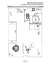

SM-2450/UHF ALIGNMENT PROCEDURE
It is important that the TCXO be on the correct frequency before performing a complete alignment of the
radio. An incorrect TCXO frequency can impair the performance and even cause mis-alignments.
Normally the transmitter is monitored with a frequency counter or service monitor while the transmitter is
keyed at its highest frequency. The TCXO is adjusted for the least frequency error. Typically the frequency
is 470MHz with a frequency error of +/- 750Hz or less. TC701 adjusts the center frequency if necessary.
PLL Alignment
•
NOTE: If the PLL is out- of- lock, an audible warning will be heard and the front panel red
LED will flash.
1. Connect an RF power meter to the ANT jack.
2. Using the channel switch, select the channel with the highest transmit frequency.
3. Connect a DC voltmeter to test point 1 ( TP1 ), accessed via the hole in the VCO cover.
4. Set the PTT switch to transmit.
5. Adjusting TC101 , set the voltage measured at TP1 to 12.0 (+/- 0.05) volts.
6. Release the PTT switch.
7. Using the channel switch, select the channel with the lowest receive frequency.
8. At TP1 measure and check that the voltage is 1.4 volts or more. If the voltage is below 1.4 volts
the VCO may not lock because the lowest RX frequency is programmed too far below the TX
frequency.
Receiver Alignment RF
• NOTE: The Receiver front end is a pre-aligned module. There are no available field
adjustments.
1. Connect an RF signal generator to the ANT socket and a SINAD meter to the external speaker
jack ( J1 ) located at the rear panel.
2. Adjust RV103 to the fully open position to hear receiver noise.
3. Adjust the VOLUME control to mid position.
4. Using the channel switch, select the programmed middle receive frequency.
5. Set the RF signal generator to the same receive channel frequency.
6. Set the audio frequency to 1kHz at 3K deviation for wide band (25kHz).
6B. Set the audio frequency to 1kHz at 1.5K deviation for narrow band (12.5kHz).
7. Adjust the RF output voltage level of the RF signal generator until the 1kHz signal is heard.
•
NOTE: The RF output voltage level and the SINAD reading.
8. Adjust T102 for an improvement in SINAD.
9. Adjust the RF output voltage level of the RF signal generator keeping the SINAD meter readings
between 6dB and 12dB .
10. Adjust T101 for an improvement in SINAD.
MAXON SM-2000 MOBILE
SM-2450/UHF ALIGNMENT PROCEDURE
Page-27-
December 98