Receiver Alignment RF
•
NOTE: The Receiver front end is a pre-aligned module. There are no available field
adjustments.
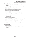
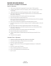
1. Connect an RF signal generator to the ANT socket and a SINAD meter to the external speaker
jack ( J1 ) located at the rear panel.
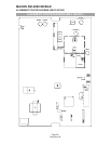
2. Adjust RV103 to the fully open position to hear receiver noise.
3. Adjust the VOLUME control to mid position.
4. Using the channel switch, select the programmed middle receive frequency.
5. Set the RF signal generator to the same receive channel frequency.
6. Set the audio frequency to 1kHz at 3K deviation for wide band (25kHz).
6B. Set the audio frequency to 1kHz at 1.5K deviation for narrow band (12.5kHz).
7. Adjust the RF output voltage level of the RF signal generator until the 1kHz signal is heard.
•
NOTE: The RF output voltage level and the SINAD reading.
8. Adjust T102 for an improvement in SINAD.
9. Adjust the RF output voltage level of the RF signal generator keeping the SINAD meter readings
between 6dB and 12dB.
10. Adjust T101 for an improvement in SINAD.
11. Adjust the RF output voltage level of the RF signal generator keeping the SINAD meter readings
between 6dB and 12dB .
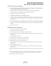
12. Check for an RF voltage signal level of 0.31uV and a SINAD meter reading of 12dB or greater.
13. Select the highest receive frequency and check for a SINAD meter reading of 12dB or greater, at
0.42uV . (Sensitivity at the operational band edge).
14. Select the lowest receive frequency and check for a SINAD meter reading of 12dB or greater, at
0.42uV.
Discriminator Tuning
1. Set the RF level to 1.0mV .
2. Adjust T103 for a maximum audio output and on the oscilloscope monitor the sinewave distortion.
Adjust T101 and T102 for lowest distortion as observed on a distortion analyzer. This is normally
less than 3%.
MAXON SM-2000 MOBILE
SM-2150/VHF ALIGNMENT PROCEDURE
Page-23-
December 98


