


THEORY OF OPERATION
Each of the Scanning Mobile radios, UHF & VHF, include a unique main P.C.B. consisting of RF, Digital
and Analog circuitry.
DIGITAL CIRCUITRY
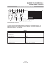
IC 411 and IC412 are digitally-controlled analog switches which internally consist of three single pole,
double throw switches. By placing a high (5V) or low (0V) on the control lines which consists of A,B, and
C. “A” controls the X ports “B” controls the Y ports and “C” controls the Z ports. Example: A high on
control “A” would connect X to X1. A low on control “A” would connect X to X0.
CTCSS/DCS Decode Circuits
Discriminator audio from Pin 9 of IC 109 is fed to IC 406 and associated parts, which are the first 2 poles
of a 6th order 250Hz Chebeyshev low pass filter. The output from Pin 1 (IC406A) is fed into IC411 (Pin 2)
and output to Pin 15 (IC411). The signal is then fed to Pin 8 (IC407) which is a 6th order low pass
Butterworth switched capacitor filter. The output from the Butterworth filter (Pin 3 IC407) is then fed to
the remaining 4 poles of the 6th order Chebeyshev, which consist of IC 406C and one of the two
operational amplifiers internal to IC407 (MF6-100) along with associated components. Both the
Chebeyshev and the Butterworth combines for a 4dB ripple low pass filter when programmed for 250Hz.
The output of IC406C(Pin 8) is fed into the remaining operational amplifier internal to IC407 (MF6-100)
which forms the squaring circuit for the Decode signal. The signal is output from Pin 2 IC407 (MF6-100)
and fed into IC409 (micro) where it is matched with a preprogrammed frequency. If successful a Decode
occurs, which is shown by a green L.E.D. on the front panel of the UHF Scanning Mobile and audio is
heard. If valid Decode was not seen, the busy L.E.D. (Yellow) would be shown.
CTCSS/DCS Encoder Circuit
During TX encode the tone squelch digital signal is produced as a 3-bit parallel word at Pins 15 (A), 16
(B), and 18C of the micro controller (IC409). The 3-bit digital signal is converted to an analog signal by
resistors R427, 428, and 430. The analog signal is fed into IC411 Pin 1. The signal is output on Pin 15
(IC411) and fed into Pin 8 of IC407 (6th order Butterworth clock tuned low pass filter). The filtered
encode output from Pin 3 (IC407) is fed into Pin 13 (IC411) and output on Pin 14 (IC411).
The filtered encode signal is fed to IC405B and RV403 (sub-audible gain control), the output of IC405B is
then fed to the audio mixer circuit.
Channel Select Circuit
One of 4 channels may be selected using the channel switch on the front panel. The channel switch SP4T
(single pole 4 throw) with output to 4 channel LED’s and to diode’s to be converted to an inverted 4-Bit
binary code. The binary code inverted is equal to the channel number. The binary code is decoded by the
micro controller enabling the appropriate RX or TX frequency and associated data to be selected from the
EEPROM.
•
NOTE:It is possible any one of the 4 channel locations can be a scanning position. Refer to
Operators Manual for further instructions.
MAXON SM-2000 MOBILE
THEORY OF OPERATION
Page-11-
December 98