


RF SECTION (SM-2450/UHF)
UHF Transmitter
The Transmitter is comprised of:
1. Microphone Audio Circuit
2. Transmitter Stage and Harmonic Filter
3. Automatic Power Control
4. Frequency Synthesizer Circuit
Microphone Audio Circuit
Microphone audio is pre-emphasized, limited and mixed with sub-audible tones to provide the modulating
signal for the transmitter. This combined modulation is applied to TCXO modulation pin 1 and also to the
VCO modulation input via RV101 to effect 2-point modulation. RV101 is a modulation balance control
that equalizes modulation sensitivities of the two oscillators.
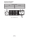
Transmitter Stage and Harmonic Filter
Power Amplifier IC103 is an RF Module. In transmit, diode D103 is forward biased allowing the RF signal
to pass to the input of IC103 via Q116 and Q117. The amplified RF output passes through the stripline
coupler and is fed to the harmonic low pass filter, consisting of spring coils L118, L120, L121 and L125
and capacitors C271, 273, 275, 277 and 280, and then to the antenna connector. The stripline coupler
provides a sample of the RF signal for automatic power control. During TX, D108 connects the power amp
to the antenna. D120 and D121 are forward biased reducing transmit signal power at the receiver input.
Automatic Power Control
The automatic power control contains the stripline coupler, diode D107, and variable resistor RV104, op
amp IC104 , and two transistors: Q124 and Q125. IC104 acts as a differential amplifier. The RF signal is
rectified by D107 to produce a DC voltage, proportional to RF power, that is applied to IC404 pin 3.
Voltage divider R168, RV104 and R170 monitors TX 8.5V dc to develop a reference for IC104A pin 2.
The difference at the output of (IC104 pin 1) is passed to Q124 and drives the collector of Q125. This
feedback controls the gain of IC103 to maintain a constant RF power output. RV104 is used to adjust the
RF high power level. RV105 is used to set the low power setting.
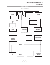
Frequency Synthesizer Circuit
With data received from the EEPROM ( IC408 ) the frequency synthesizer circuit controls and produces
the RF carrier frequency for the transmitter during transmit and the local oscillator frequency for the
receiver.
The frequency synthesizer circuit is comprised of:
1. RX and TX voltage controlled oscillator module.
2. Loop Filter
3. PLL Frequency Synthesizer
MAXON SM-2000 MOBILE
THEORY OF OPERATION
Page-18-
December 98