


RX VCO
The RX VCO comprises JFET Q351, coil L356 and varactor D353 and is configured as a Colpits oscillator.
D353 produces a change in frequency with a change in DC voltage and is controlled by the phase detector
signal present at the anode. The local oscillator signal at the drain of Q351 is applied to RF out of the
module when diode D103 is reverse biased and D104 is forward biased. L356 is used for PLL alignment.
TX VCO
The TX VCO comprises JFET Q352 coil L353 and varactor D352 and is configured as a colpits oscillator.
The AF signal at MOD port is applied to the cathode of D352. The control voltage from the loop filter is
applied to the drain of Q352 and is passed to the power amplifier and harmonic filter via the buffer Q113
and Q114. When diode D103 is forward biased and D104 is reversed biased L353 is used for PLL
alignment.
Loop Filter
Transistor Q101 to Q104 and associated components form a loop filter. The phase detector from Pin3 and
4 of IC101 are filtered to remove any reference frequency harmonics and applied to the voltage controlled
oscillator.
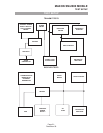
PLL Frequency Synthesizer
The PLL frequency synthesizer (IC101) contains an oscillator for the reference divider, a programmable
divider, a phase/frequency Comparator and an out of lock detector and a Prescaler.
Reference Oscillator
The reference oscillator of IC01 along with a 10.25 or 12.8MHz TCXO, varactor diode D701 and D702,
and the thermistors TH701, TH702, and TH703 produce a temperature compensated 10.25 or 12.8MHz
reference.
Programmable Dividers
The serial frequency data (DATA) is received by the data programmable divider at Pin 19 of IC101 from
Pin 1 of IC409 (Micro controller) out. The internal Prescaler divided input frequency at pin 11 of IC1 is
further divided by the programmable divider. The 10.25 or 12.8MHz TCXO frequency at pin 20 is the
reference divider to produce a reference frequency of 5 or 6.25kHz respectively. The internal
programmable divided frequency (Fv) and the reference frequency (Fr) are fed to the internal phase
detector.
Phase Detector
The phase detector produces negative pulses when Fv < Fr, positive pulses when Fv>Fr. When Fv = Fr and
phase is the same, the phase detector presents a high impedance at Pin 4. The signal at Pin 2 is applied to
the VCO via the loop filter.
MAXON SM-2000 MOBILE
THEORY OF OPERATION
Page-15-
December 98