112 EuroPak-15a Receiver User Manual Rev 5
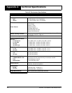
Appendix A Technical Specifications
INPUT/OUTPUT DATA INTERFACE
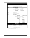
COM1 AND COM2
Electrical format
RS232
Bit rate
a
9600 (default), 19200, 38400, 57600, 115200, 230400 bps
Signals supported
TX, RX, RTS, CTS, DTR, DCD
a. Baud rates higher than 115,200 bps are not supported by standard PC hardware. Special PC hardware is re-
quired for higher rates, including 230,400 bps.
INPUT/OUTPUT STROBES
MSR (Measure Output) Normally high, active low where the pulse width is 1 ms. The falling edge is the
receiver measurement strobe.
MKI (Mark Input) An input mark (negative pulse > 55 ns), time tags output log data to the time of
the falling edge of the mark input pulse.
PV (Position Valid) Output indicates a ‘good solution’ or a valid GPS solution when high.
ERROR Output that Indicates fatal error warning when high.
PPS (Pulse Per Second) Normally high, active low pulse is 1 ms wide @ 1 Hz. Falling edge is used as
the reference.
RESETOUT
Reset TTL signal output to external system; active high.
STROBE ELECTRICAL SPECIFICATIONS
Output Voltage: LVTTL levels
Low:
High:
minimum 0 VDC and maximum 0.55 VDC @ 24 mA
minimum 2.4 VDC and maximum 3.6 VDC @ 8 mA
Input Voltage: LVTTL levels
Low:
High:
minimum 0 VDC and maximum 0.8 VDC
minimum 2.0 VDC and maximum 5.5 VDC


