


24 EuroPak-15a Receiver User Manual Rev 5
Chapter 2 Installation
NovAtel-supplied accessories.
2.1.3 Power Supply Requirements
This section contains information on the requirements for the input power to the receiver. See Appendix A,
Technical Specifications starting on Page 110 for more power supply specifications.
WARNING: If the voltage supplied is below the minimum specification, the receiver will suspend
operation. If the voltage supplied is above the maximum specification, the receiver may
be permanently damaged, voiding your warranty.
The receiver is designed to prevent internal damage when subjected to a reverse polarity power connection. It
also provides protection from short over voltage events. It is recommended that appropriate fuses or current
limiting be incorporated as a safety precaution on all power lines used. Use a sufficient gauge of wire to ensure
that the voltage at the connector is within the receiver’s requirements.
2.1.3.1 EuroPak-15a Enclosure
The EuroPak-15a is supplied with a 12 V power adapter with a built-in slow-blow fuse for use with a standard
12 VDC power outlet.
If a different supply is desired, the input range required is +9 to +18 VDC. The type of connector required to
mate with the receiver’s power connector is a 4-pin LEMO socket connector labelled PWR. The supply should
be capable of 15 W. See Appendix D, Replacement Parts starting on Page 126 for the LEMO connector part
number.
2.2 Installation Overview
Once you have selected the appropriate equipment, complete the following steps to set up and begin using your
NovAtel receiver.
1. Mount the antenna or signal generator to a secure, stable structure, see Section 2.2.1 on Page 25.
2. Connect the antenna or signal generator to the receiver with an RF cable, using the information
given in Section 2.2.2 on Page 25.
3. Apply power to the receiver, as described in Section 2.2.3 on Page 26.
4. Connect the receiver to a PC or other data communications equipment by following the
information given in Section 2.2.4 on Page 26.
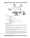
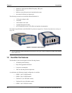
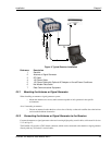
Figure 3 on the next page shows a typical set up for an enclosed receiver.