


9
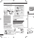
Connecting the System
ENG/MASTER 96
10
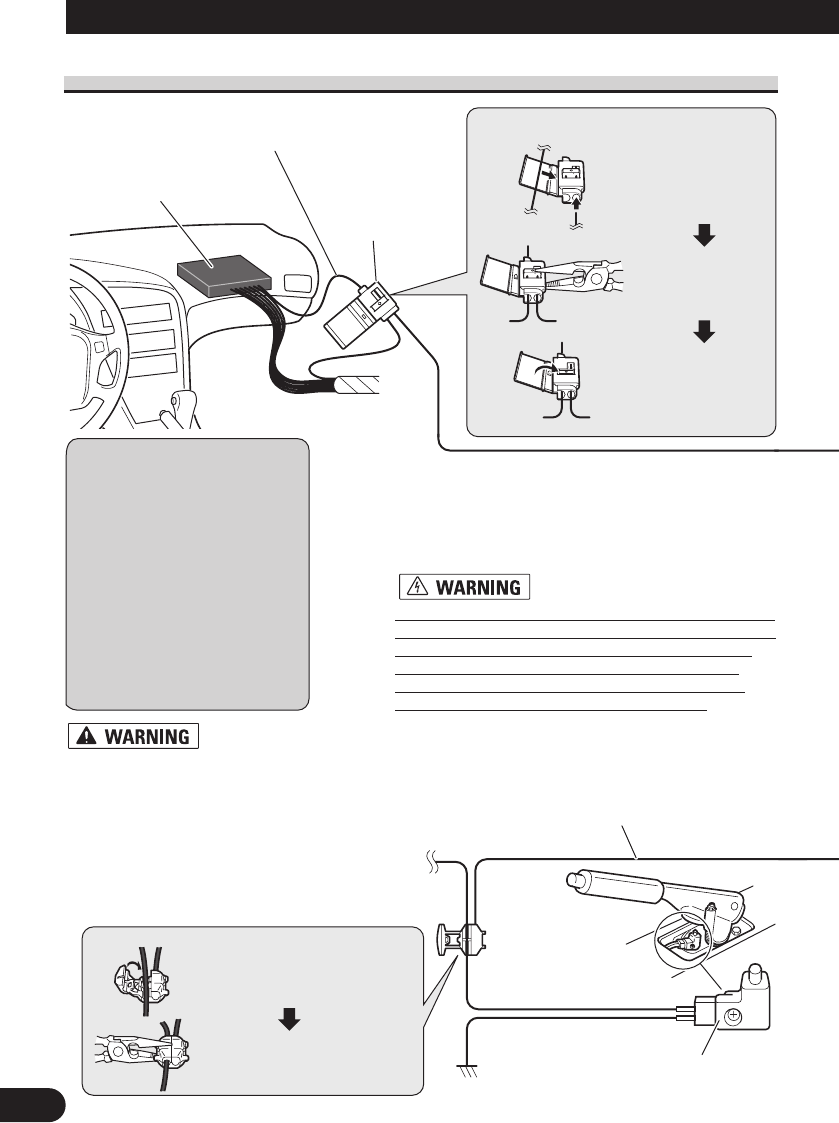
Connecting the power cord (1)
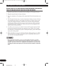
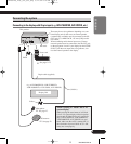
Connector
Speed detection circuit lead
Vehicle injection computer
Connection method
Pass the extension cord
and the lead for the
speed detection circuit
through this hole.
Clamp firmly with
needle-nosed pliers.
Close the cover.
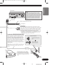
Note: The position of the speed
detection circuit depends on the
vehicle model. For details, consult
your authorized Pioneer dealer or
an installation professional. If con-
nection to the speed detection cir-
cuit is too difficult, connect the
separately sold ND-PG1 speed
pulse generator to the pink lead.
Note: The position of the parking
brake switch depends on the vehi-
cle model. For details, consult the
vehicle owner’s manual or dealer.
Connection method
Clamp the parking brake
switch power supply side lead.
Clamp firmly with
needle-nosed pliers.
Power supply side
Ground side
Parking brake switch
Pink (CAR SPEED SIGNAL INPUT)
The navigation system is connected here to detect the dis-
tance the vehicle travels. Always connect the vehicle’s
speed detection circuit or the ND-PG1 speed pulse genera-
tor, sold separately. Failure to make this connection will
increase in the location display.
IMPROPER CONNECTION MAY RESULT IN SERI-
OUS DAMAGE OR INJURY INCLUDING ELECTRI-
CAL SHOCK, AND INTERFERENCE WITH THE
OPERATION OF THE VEHICLE’S ANTILOCK
BRAKING SYSTEM, AUTOMATIC TRANSMIS-
SION AND SPEEDOMETER INDICATION.
Light green
Used to detect the ON/OFF status of the parking brake.
This lead must be connected to the power supply side of
the parking brake switch. If this connection is made
incorrectly or omitted, certain functions of your naviga-
tion system will be unusable.
LIGHT GREEN LEAD AT POWER CON-
NECTOR IS DESIGNED TO DETECT
PARKED STATUS AND MUST BE CON-
NECTED TO THE POWER SUPPLY
SIDE OF THE PARKING BRAKE
SWITCH. IMPROPER CONNECTION
OR USE OF THIS LEAD MAY VIOLATE
APPLICABLE LAW AND MAY RESULT
CRD3914A_inst_001_030_Eng 5/11/04 4:40 PM Page 10