


www.ti.com
System Setup
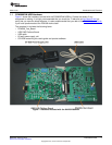
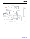
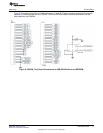
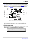
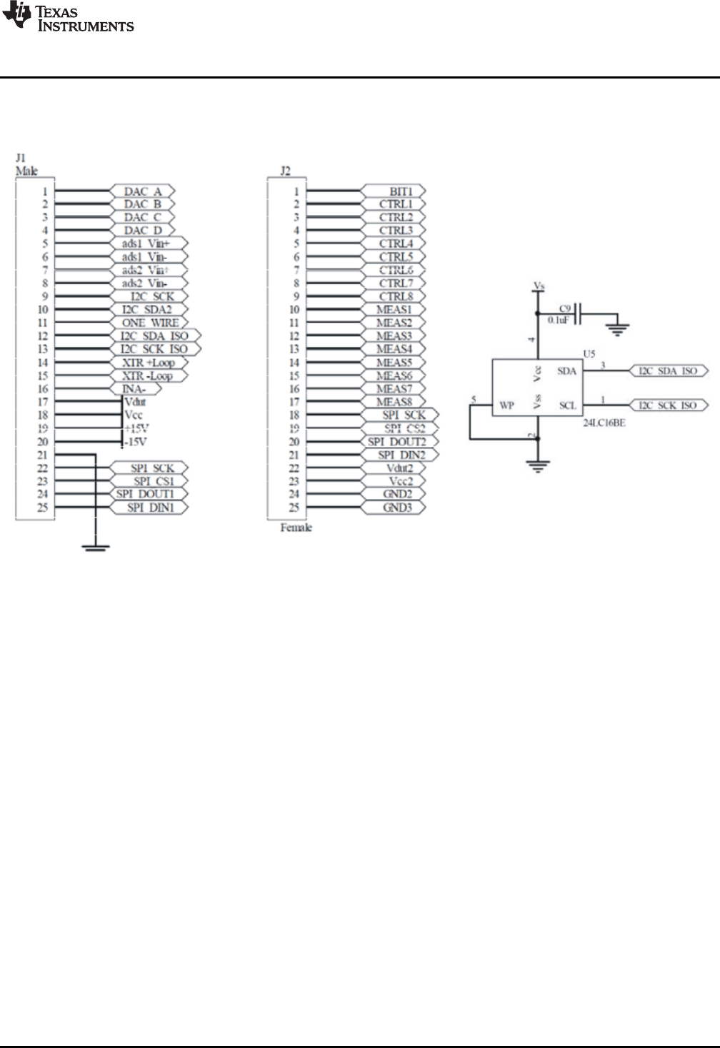
Figure 8 illustrates the two 25-pin D-SUB connectors J1 and J2. These connectors provide all the signals
necessary to communicate with the PGA309. U5 is the EEPROM used to store the calibration look-up
table used with the PGA309.
Figure 8. PGA309_Test_Board Connections to USB-DAQ-Platform and EEPROM
11
SBOU084–February 2010 PGA309EVM-USB
Submit Documentation Feedback
Copyright © 2010, Texas Instruments Incorporated