


USBDAQ
Platform
PGA309
TestBoard
EVM
Power
PGA309
V Supply
Switched5.0VPower
DUT
One-WireInterface
25-Pin
MaleDSUBSignals
FromUSBDAQPlatform
25-Pin
FemaleDSUBSignals
FromUSBDAQPlatform
I C
Interface
2
4mAto20mA
I/VConverter
Sensor
Connection
Sensor
Emulator
www.ti.com
System Setup
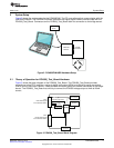
2 System Setup
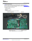
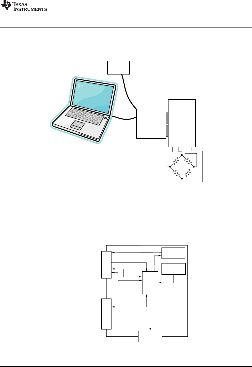
Figure 2 shows the system setup for the PGA309EVM. The PC runs software that communicates with the
USB-DAQ-Platform. The USB-DAQ-Platform generates the digital signals used to communicate with the
PGA309_Test_Board. Connectors on the PGA309_Test_Board allow for connection to the bridge sensor.
Figure 2. PGA309EVM-USB Hardware Setup
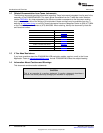
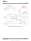
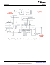
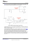
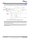
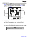
2.1 Theory of Operation for PGA309_Test_Board Hardware
Figure 3 shows the block diagram of the PGA309_Test_Board. The PGA309_Test_Board provides
connections to the I
2
C™, one-wire, analog-to-digital converters (ADCs) and digital-to-analog converters
(DACs) on the USB-DAQ-Platform. It also provides connection points for external connection of the bridge
sensor. The PGA309_Test_Board has circuitry to convert the PGA309 voltage output to 4mA to 20mA
current.
Figure 3. PGA309_Test_Board Block Diagram
5
SBOU084–February 2010 PGA309EVM-USB
Submit Documentation Feedback
Copyright © 2010, Texas Instruments Incorporated