


www.ti.com
PGA309EVM-USB Hardware Setup
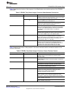
Table 5 describes the function of the jumpers in the Miscellaneous connections section of the PGA309
Test Board.
Table 5. PGA309_Test_Board Jumper Functions: Miscellaneous Connections
Jumper Default Purpose
JMP1, JMP2 NC For JMP1 = NC, JMP2 = V
REF
EXT: The REF pin on the
PGA309 is configured for internal reference. In this mode, JMP2
is not connected, so its position does not matter.
V
REF
EXT For JMP1 = V
REF
, JMP2 = V
S
: The REF pin is configured for
external reference and is connected to V
S
.
For JMP1 = V
REF
, and JMP2 = V
REF
EXT: The REF pin is
configured for external reference and is connected to T2
(terminal for external reference connection).
JMP3 ADS1 For JMP3 = ADS1, it connects the analog-to-digital converter
(ADC) on the USB-DAQ-Platform to the output of the PGA309.
The ADC on the USB-DAQ-Platform allows full measurement
and calibration of the PGA309 without any additional
instruments.
For JMP3 = NC, the ADC on the USB-DAQ-Platform is not
connected to the PGA309. This mode is useful if you want to
use an external DMM in place of the USB-DAQ ADC.
JMP7, JMP8 NC For JMP7 = NC, and JMP8 = One to PRG: In this mode, the
one-wire signal from the USB-DAQ-Platform is connected
directly to the PRG pin on the PGA309. This mode is commonly
called Four-wire mode because only four connections are
required (Power, GND, V
OUT
, and PRG).
One to PRG For JMP7 = V
OUT
to PRG, and JMP8 = One to V
OUT
: In this
mode, the one-wire signal from the USB-DAQ-Platform is
connected to the V
OUT
/PRG pin on the PGA309. This mode is
commonly called Three-wire mode because only three
connections are required (Power, GND, and V
OUT
/PRG).
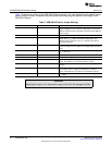
Table 6 explains the function of the jumpers in the sensor emulator section connections section of the
PGA309 Test Board.
Table 6. PGA309_Test_Board Jumper Functions: Sensor Emulator Section
Jumper Default Purpose
JMP12 V
EXC
This jumper selects V
S
or V
EXC
as the reference for the sensor
emulator. Using V
S
as the reference is commonly called
ratiometric mode.
JMP17, JMP4, JMP5, JMP6 Emulate These jumpers select the sensor emulator when in the Emulate
position. When the jumper is in the EXT position, it selects the
external sensor.
JMP14, JMP15 10mV These jumpers select the range of the sensor emulator.
This jumper is used for the sensor emulator only; its position is
not important for externally-connected, real-world sensors.
10m = maximum emulator output is 10mV/V.
100m = maximum emulator output is 100mV/V.
JMP13, JMP16 RT–, Diode This jumper selects the type of temperature sensor you will
emulate on the EVM. This jumper is used for the sensor
emulator only; its position is not important for
externally-connected, real-world sensors.
JMP13 = Diode, JMP16 = RT-. In this position, the temperature
sensor emulation is set for diode type temperature sensor.
When JMP13 = Diode, the position of JMP16 does not matter.
JMP13 = RT, JMP16 = RT-. In this position, the temperature
sensor emulation is set for RT–.
JMP13 = RT, JMP16 = RT+. In this position, the temperature
sensor emulation is set for RT+.
23
SBOU084–February 2010 PGA309EVM-USB
Submit Documentation Feedback
Copyright © 2010, Texas Instruments Incorporated