


PGA309EVM-USB Hardware Setup
www.ti.com
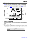
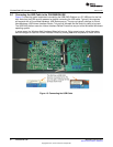
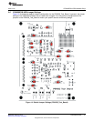
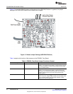
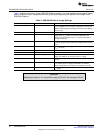
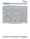
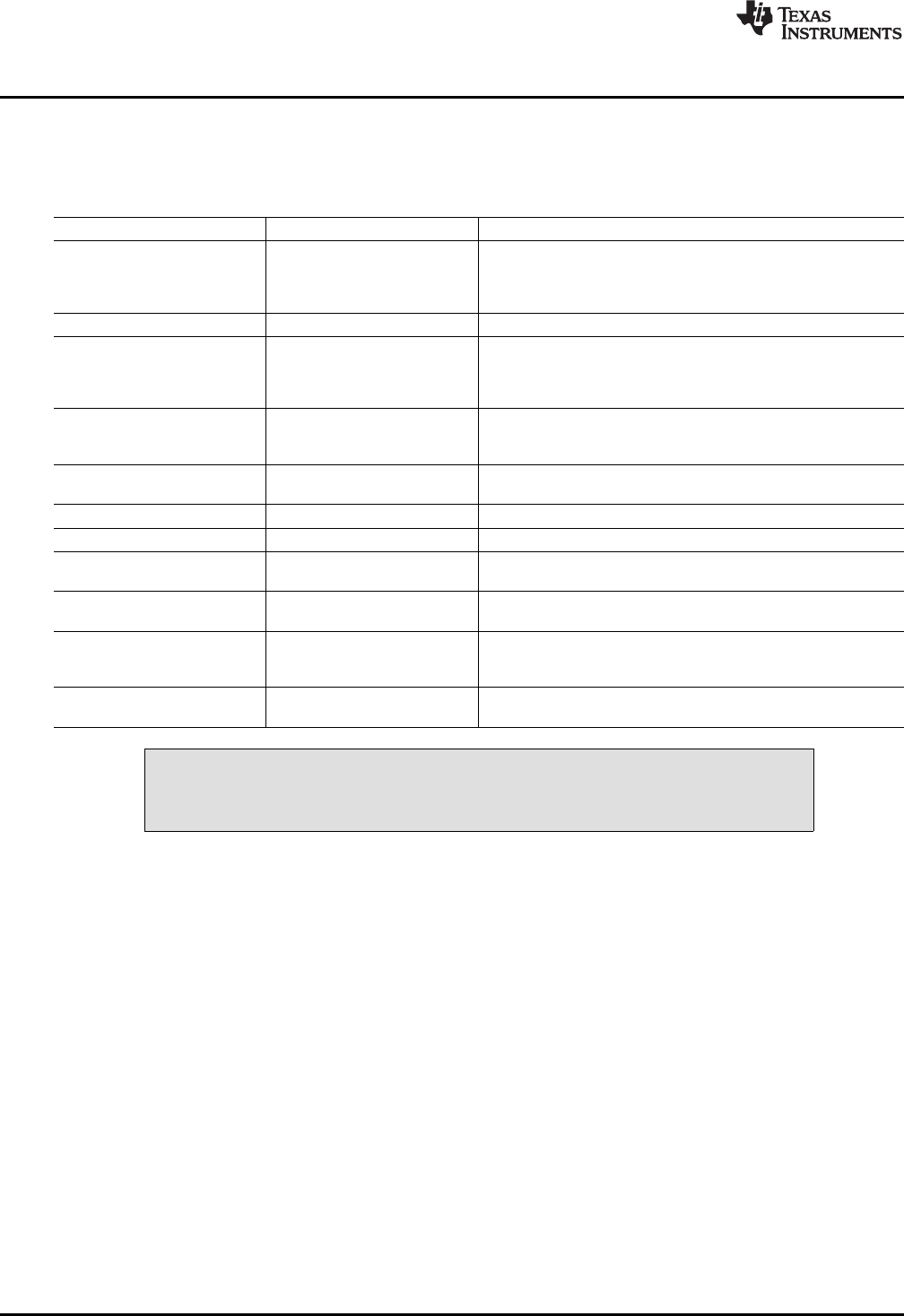
Table 7 explains the function of the USB-DAQ-Platform jumpers. For most applications the default jumper
position should be used. A separate document gives details regarding the operation and design of the
USB-DAQ-Platform.
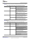
Table 7. USB-DAQ-Platform Jumper Settings
Jumper Default Purpose
JUMP1 EXT This jumper selects external power or bus power. External
power is applied on J5 or T3 (9V dc). Bus power is 5V from the
USB bus. External power is typically used because the USB bus
power is noisy.
JUMP2 EXT Same as JUMP1.
JUMP3 EE ON This jumper determines where the PGA309 gets its power
supply. In the V
DUT
position, the EVM provides power. The
default is the V
DUT
position. In the V
S_Ext
position, the power is
connected externally.
JUMP4, JUMP5 L, L This jumper sets the address for the USB board. The only
reason to change from the default is if multiple boards are being
used.
JUMP9 5V This jumper selects the voltage of the device under test supply
(V
DUT
= 5V or 3V)
JUMP10 WP ON This jumper write-protects the firmware EEPROM.
JUMP11 WP ON This jumper write-protects the calibration EEPROM
JUMP13 Reg This jumper configures the regulator output to generate the V
DUT
supply. The USB bus can be used as the V
DUT
supply.
JUMP14 9V This jumper configures the external power (9V as apposed to
the bus)
JUMP17 BUS While in the BUS position V
DUT
operation is normal. While in the
V
RAW
position, the V
DUT
supply is connected to an external
source. This allows for any value of V
DUT
between 3V and 5V.
JUMP18 V
DUT
Connects the pull-up resistor on GPIO to the V
DUT
supply or the
V
CC
supply.
CAUTION
Adjusting the value of V
DUT
beyond the range of 3V to 5V will damage the EVM.
24
PGA309EVM-USB SBOU084–February 2010
Submit Documentation Feedback
Copyright © 2010, Texas Instruments Incorporated