


43-EN
ALPINE DHA-S690 68-09359Z17-A (EN)
•
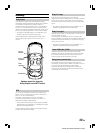
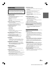
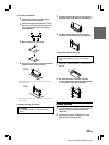
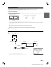
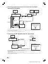
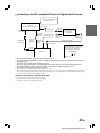
Connecting an Ai-NET compatible AV head unit / Digital Audio Processor
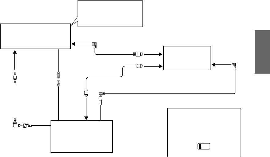
DHA-S690
AV Head Unit
IVA-D105R, etc. (sold separately)
Ai-NET Connector
Ai-NET Cable
Ai-NET Input
Connector
Ai-NET Input
Connector
(CHANGER IN)
Digital Audio Processor
PXA-H701, etc.
(sold separately)
Digital Input
Terminal (Optical)
(Changer)
Digital Output
Terminal
(Optical)
Fiber Optic Cable
(sold separately)
Ai-NET Cable (included)
Ai-NET Connector
AUX Video
Input Terminal
Remote Control
Output Lead
(white/brown)
Remote Control
Input Lead
(white/brown)
Video Output
Connector
Change the system switch on the AV
head unit to “EQ/DIV”.
RCA Extension
Cable (included)
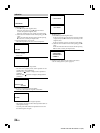
• Be sure to switch the head unit’s system switch before turning the power on.
• Be sure to make the setting (DVD CHG or CD CHG) in “Setting the Connected Head Unit” (page 21) according to the connected Ai-NET
compatible head unit.
• If CD CHG is set in “Setting the Connected Head Unit” (page 21):
If you want to play back a DVD Audio, set “Switching the input (non Ai-NET connections)” on the connected Alpine audio processor
(PXA-H700, PXA-H701) to “Analog.” For details on operation, refer to the Owner’s Manual of the audio processor.
• The switched Power Lead (Ignition) connection is not needed.
• Also refer to the operating instructions of the other products in the system.
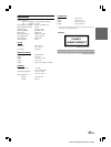
•When connecting the optical digital output to a digital audio processor, be sure to make connection to the CHANGER connectors of the digital
audio processor optical digital input connectors. This arrangement allows you to enjoy Dolby Digital 5.1 Channel Surround and other effects
even when connection is made to the CHANGER connectors.
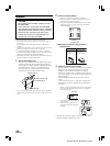
Observe the following when using Fiber Optic Cable.
• Be careful not to bend the fiber optic cable at a sharp angle.
• Do not coil the fiber optic cable smaller than a 30 mm radius.
• Do not place anything on top of the fiber optic cable.
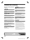
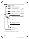
Setting of DHA-S690
The DHA-S690’s system settings must be
made after connections are completed.
Before fixing the unit in place, refer to
page 41 to change the system setting.
System Switch
12
Switches to “1”.