


MAN 650066:D
10
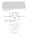
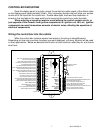
SPD +
This terminal is used to supply power to Dakota Digital speed sensor SEN-01-5. This
supplies 5V DC to the sensor and should not be hooked up to anything else. Connect the red
wire from the SEN-01-5 to this terminal.
If you are using a 1-wire VSS output from a computer or a two wire pulse generator this
terminal should be left open.
***DO NOT use this terminal to power any other devices it is a low current +5V output.
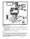
SPD SND
This is where the vehicle speed sensor (VSS) connects. The signal supplied to this
terminal will be used by the control box to calculate the speed reading on the display and also
for calculating and saving odometer mileage.
Dakota Digital supplies a 3-wire sensor for most of its kits, SEN-01-5. If you are using
this sensor, the white wire is the speed signal; connect to SPD SND. The red and black wires in
the cable are power and ground (5V DC) and their connection is discussed in SPD + and SPD -.
For two wire speed sensors such as a cable driven pulse generator, the polarity of the
wires does not matter. Connect one wire to the SPD – (Ground) and the other to the SPD SND
terminal. The speed sensor ground wire should be brought back to the control box to ensure a
proper signal is received. Twisting the ground and signal wires around each other provides an
additional level of interference protection. The speed signal wire should not be routed alongside
tach, ignition, or other high current or high voltage wires.
For vehicles which have a vehicle speed signal from a transmission sensor or ECM, tap
into the VSS wire and connect it to the SPD SND. Consult a vehicle service manual or wiring
diagram to determine wire color and location.
This system can accept 4000 ppm – 128,000 ppm speed signals with room for
adjustment. The speedometer is fully adjustable and calibration is discussed in a later section.
***Failure to calibrate the speedometer may cause your odometer mileage to
increase very rapidly if the speedometer is reading too fast.
*** The speed signal wire should NOT be routed alongside ignition or other high
current/voltage wires.
SPD –
This terminal is used for speed sensor ground. This insures a proper ground as well as
providing proper hook-up for a twisted pair of wires, or a solid state sensor. Only ground the
speed sensor here. If you are using a single wire output from a computer for the VSS then this
terminal should be left open.
SPD OUT
This terminal can be used to supply a speed signal to auxiliary devices such as a cruise
control or radio volume adjustment. The output is scaled to the input speed signal coming into
the SPD SND terminal. It can be set to 2000 PPM or 4000 PPM.
***If you are using the bus speed signal option this output will NOT work.
SW 2 (-) or Tach switch
The SW 2 terminal is used for selecting the various rpm, engine, and warning displays
and also for entering the demonstration mode. The SW 2 input is activated by a ground
connection. The push button switch supplied (or any momentary normally open switch) is wired
by connecting one terminal to SW 2 and the other terminal to a ground. When the button is
pressed and released, the tach message display will change. When the button is pressed and
held for a few seconds, any re-settable information displayed will be zeroed. On systems with
two message displays, the one below the tach is dedicated to rpm/warn messages. On