


MAN 650066:D
11
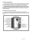
systems with one message display the speed/performance and rpm/warn messages will use the
same display.
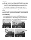
To enter DEMO mode, press and hold switch 2 while turning the key on. The system will
light up and say DAKOTA DIGITAL on the message readouts, release the switch and the
system will stay in demo mode until the power is cycled off and back on without the switch held.
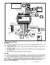
SW 1 (-) or Speed switch
The SW 1 terminal is used for selecting the various speed, distance, and performance
displays and also for entering the setup menu. The SW 1 input is activated by a ground
connection. The push button switch supplied (or any momentary normally open switch) is wired
by connecting one terminal to SW 1 and the other terminal to a ground. When the button is
pressed and released, the speed message display will change. When the button is pressed and
held for a few seconds, any re-settable information displayed will be zeroed. On systems with
two message displays, the one below the speed is dedicated to speed/performance messages.
On systems with one message display the speed/performance and rpm/warn messages will use
the same display.
ADJ SND
The ADJ SND terminal is an optionally used input that allows you to have control over the
dimming brightness. By default, the system will dim to approximately half brightness when the
DIM terminal has power, +12V, but this level is adjustable in the NIGHT setup menu. Using the
A
DJ SND terminal allows you to have a dash mounted control to vary the brightness while the
headlights are on. This requires Dakota Digital’s DIM-1 kit; a stock headlight rheostat will not
work.
The DIM-1 has two wires, one connects to the ADJ SND terminal and the other connects
to ADJ - ground. The dash mounted dimmer will only vary the display brightness when the DIM
terminal has power, +12V.
ADJ –
This terminal provides a ground reference for the optionally installed DIM-1 for dash
mounted dimming control. One wire from the potentiometer will connect to the ADJ – terminal,
the other connects to the ADJ SND.
*This terminal should not be used for grounding other sensors or devices or damage to
the control box will occur. If not using a Dakota Digital DIM-1, this terminal should be left
open.
WTR SND
The water temperature sender included with this system must be used. Other
senders will cause incorrect readings or damage to the control box.
The supplied sensor, Dakota Digital SEN-04-5, is a 100-300ºF(40-150ºC) temp sensor.
The sender mounts on the engine block or into the intake manifold so that the end of the sensor
is in the engine coolant flow. It has 1/8” NPT threads, adaptor bushings may be used to adapt it
for various applications.
The water temp sensor has two wires coming from the harness. One wire will connect to
the WTR SND terminal; the other wire will connect to the WTR –. It does not matter which wire
goes into either location.
Due to the construction of the sensor, readings at lower temperatures below 100 ºF will
be inaccurate. The sensor is designed to be accurate from approximately 100 ºF - 300 ºF.