


MAN 650066:D
9
POWER
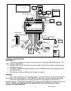
Connect the POWER terminal to accessory +12V power from the fuse panel or vehicle
wiring harness. This terminal should have power when the key is on or in accessory position.
In addition to powering the display system, this is also where the voltmeter gauge senses the
vehicle electrical system voltage. The supply source should be a fused 5 - 20 amp circuit, the
system only draws about 1 amp, so sharing an existing accessory circuit will be generally be
fine. Use 18 AWG wire to ensure the system receives a sufficient power feed.
*** Never connect this to a battery charger alone. It needs to have a 12 volt battery
connected to it. Battery chargers have an unregulated voltage output that will cause the
system to not operate properly and may cause damage to the control box.
TACH
Depending on the type of instrument system that you have, there may be a bar graph
tachometer, a digital tachometer, or both. Connect the TACH terminal to the ignition system.
On vehicles using a separate ignition coil, connect to the negative side of the coil. The negative
side of the coil will be the wire that goes to the points or electronic ignition module. For GM HEI
ignition equipped motors, connect to the terminal marked “TACH” or on some systems a single
white wire with a spade terminal on it. On some aftermarket ignition systems, connect to the
TACH output terminal. On computer controlled ignition systems consult a service manual for
the wire color and location. With a magneto system, connect to the kill wire for the tach signal.
Do not connect the TACH terminal to the secondary, or high voltage side of the ignition
coil.
To ensure that the ignition system does not interfere with any other dashboard functions,
do not run the tachometer wire alongside any other sender or input wires. DO NOT USE SOLID
CORE SPARK PLUG WIRES WITH THIS DASHBOARD SYSTEM. Solid core ignition wires
cause a large amount of electromagnetic and radio frequency interference which can disrupt the
system operation.
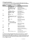
The tachometer is compatible with almost all gasoline engines. The engine cylinder
selection, display update rate, tach signal type, and rpm warning point can be adjusted in the
setup menu under “TACH”. If a diesel engine is being used then you will n
eed a tach interface,
such as Dakota Digital’s DSL-1 or DSL-2. Be aware of the cylinder setting when using computer
outputs or reading the tach signal from an ECU. GM LS1 engines require the tach to be set up
for a 4 cylinder, low voltage signal when reading from the ECU even though it is a V8 engine.
WARN
The WARN terminal is an output for a relay or small light. The output is ground-activated
when the preset rpm limit is exceeded. This output can turn on a 4 Watt or smaller 12 volt bulb
or can activate a relay to turn on a larger bulb. To wire a warning light to this output, connect
one wire from the bulb to 12 volt accessory power and connect the other wire to the WARN
terminal.
DIM
The gauges are designed to dim down when the headlights are turned on. This is to
reduce the display intensity at night so the gauges do not cause eye strain or reduced night
vision. Connect this to the tail light or parking light circuit so that it has 12 volts whenever the
headlights are on. When this terminal does not have power the display system will be at full
brightness. When power is applied, the display dims to an adjustable level.
The night brightness level is adjustable two different ways. This preset brightness is
adjusted in the setup menu “NIGHT
N
IGHTNIGHT
NIGHT”. See ADJ SND for a description of the second method.
By default the system will dim to a about ½ bright ness when DIM terminal gets +12V.