


MAN 650066:D
20
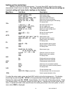
Display update setup (UPDATE
UPDATEUPDATE
UPDATE)
The display update rate can be adjusted so the reading on the tachometer doesn’t
change so quickly. This is a personal preference and is just used to “slow” the reading by
averaging. The value can be changed from slow, mid, and fast.
• When “UPDATE
UPDATEUPDATE
UPDATE” is displayed press and hold SW1 until you get “ - ”
• Release SW1 and the current update rate will be displayed.
• Press and release SW1 to increase the value from “SLOw
SLOwSLOw
SLOw” “ MID
MIDMID
MID” “ FAST
FASTFAST
FAST”
• When the desired setting is displayed press and hold SW1 until “ - ” “DONE
DONEDONE
DONE” is displayed
• Release the switch to go onto the next sub-menu item.
Rpm warning setup (WARN
W
ARNWARN
WARN)
This is used for the turn on point for the WARN output on the control box. When the rpm
reading is above this setting, the output will activate, providing a ground signal. It can be used
to turn on a shift light or other rpm based devices. The value is adjustable from 2200 RPM –
14800 RPM in 100 RPM increments.
• When “WARN
WARNWARN
WARN” is displayed press and hold SW1 until you get “ - ”
• Release SW1 and the current warning point will be displayed
• Press and release SW1 to increase the value from “W 2200
W 2200W 2200
W 2200” – “W14800
W14800W14800
W14800”
• When the desired setting is displayed press and hold SW1 until “ - ” “DONE
DONEDONE
DONE” is displayed
• Release the switch to go onto the next sub-menu item.
Tach signal setup (SIGNAL
SIGNALSIGNAL
SIGNAL)
This menu will allow you to select from two different tach-input types. A low voltage, “5
5 5
5
LO
LOLO
LO”, tach signal or a high voltage tach signal, “12 HI
12 HI12 HI
12 HI”. A low voltage signal is usually one that
would be picked up from the ECM. Low voltage may also be considered a 0-5V square wave.
If you are getting the tach signal from the ignition coil or points, set this for the high voltage
signal“12 HI
12 HI12 HI
12 HI”. To pick up a tach signal form a traditional coil you would want to wire it to the
negative side of the coil.
• When “signal
s
ignalsignal
signal” is displayed press and hold SW1 until you get “ - ”
• Release SW1 and the current value will be displayed.
• Press and release SW1 to toggle from “12 HI
12 HI12 HI
12 HI” to “5 LO
5 LO5 LO
5 LO”
• When the desired setting is displayed, press and hold SW1 until “ - ” “DONE
DONEDONE
DONE” is displayed
• Release the switch to go onto the next sub-menu item.
Exit tach setup (done
donedone
done)
This will allow you to exit the tach setup and go on to the next setup menu.
• When “Se
SeSe
Set
done
donedone
done” is displayed, press and hold SW1 until you get “ -
--
- DONE
DONE DONE
DONE ”
• Release the switch to go onto the next menu
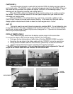
VOLT SETUP
The volt setup allows you set a warning point that will cause the volt display to flash
whenever the voltage drops below the warning value. The low voltage point can be set from 10
-13.1 volts.
• Press and hold SW 1 while turning the key on.
• Release the switch and then press and release SW1 to get to the “volt
voltvolt
volt” setup menu.
• When “volt
voltvolt
volt” is displayed press and hold SW1 until you get “ - ”, release SW1 and “WARN
WARNWARN
WARN”
will be displayed.
• When “WARN
W
ARNWARN
WARN” is displayed press and hold SW1 until you get “ - ”
• Release SW1 and the current warning point will be displayed
• Press and release SW1 to increase the value from “LO 10.0
LO 10.0LO 10.0
LO 10.0” – “LO 13.1
LO 13.1LO 13.1
LO 13.1”
• When the desired setting is displayed press and hold SW1 until “ - ” “DONE
DONEDONE
DONE” is displayed
• Release the switch to go onto the next sub-menu item.