


MAN 650066:D
19
Speed Output (OUTPUT
OUTPUTOUTPUT
OUTPUT)
If a speed signal is needed for an ECM or cruise control, the SPD OUT terminal can be
used. This terminal can supply a 2000 ppm or 4000 ppm signal.
• When “output
outputoutput
output” is displayed, press and hold SW1 until you get “ - ”
• Release the switch. The current PPM output will be displayed.
• Press and release SW1 to toggle from “ 2k PPM
2k PPM 2k PPM
2k PPM” to “ 4k PPM
4k PPM4k PPM
4k PPM”.
• When the desired setting is displayed, press and hold SW1 until “ - ” “DONE
DONEDONE
DONE” is displayed
• Release the switch to go onto the next menu item.
Exit setup (done
d
onedone
done)
This will allow you to exit the speed setup and go on to the next setup menu.
• When “Se
SeSe
Set
done
donedone
done” is displayed, press and hold SW1 until you get “ -
--
- DONE
DONE DONE
DONE ”
• Release the switch to go onto the next menu
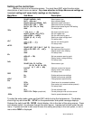
TACHOMETER SETUP
The control box can be set to read from 1-16 cylinder ignition signals. It can also be set
to read either 12 volt tach signals or 5 volt tach signals found on some engine computers. The
digital tachometer update rate can be adjusted between slow, mid, and fast. The rpm
warning/shift point can be adjusted from 2200 – 14800. The tachometer will read from 350 –
17,500 rpm. At rpm’s above 9990 the reading will be displayed as rpmx1000 (12,000=12.00).
You can also read the tach signal with the use of a future bus interface module (BIM).
Dakota Digital offers a BIM that will allow you to read the speed signal from an ECU if you are
installing the system in a vehicle equipped with the OBDII port or a drive train from a newer
vehicle, most 1996 and newer vehicles have this.
• Press and hold SW 1 while turning the key on.
• Release the switch and then press and release SW1 to get to the “TACH
TACHTACH
TACH” setup menu.
• Press and hold the switch until “- tach” is displayed to enter the tach setup menus, then
release SW1.
• Now you can press and release the switch to scroll through the tach sub-menus, “T CAL
T
CALT CAL
T CAL”
“UPDATE
UPDATEUPDATE
UPDATE” “WARN
WARNWARN
WARN” “SIGNAL
SIGNALSIGNAL
SIGNAL” “DONE
DONEDONE
DONE”.
• When you get to the desired sub-menu, press and hold the switch to select it.
Engine cylinder setup (T
TT
T-
--
-CAL
CALCAL
CAL)
This menu is used to set the current number of cylinder that the tach signal is providing.
It is adjustable from 1 -16 cylinders.
• When “T
TT
T-
--
-CAL
CALCAL
CAL” is displayed, press and hold SW1 until you see “ - ”
• Release SW1 and the current cylinder setting will be displayed.
• Press and release SW1 to increase the value from “ 01
01 01
01 ” – “ 16
16 16
16 ” or “ bus
busbus
bus
”
• When the desired setting is displayed, press and hold SW1 until “ - ” “DONE
DONEDONE
DONE” is displayed
• Release the switch to go onto the next menu item.
NOTE: When selecting the cylinder count, be aware of tach signals coming from ECMs,
oftentimes a V-8 engine computer may output a 4 cylinder tach signal. This will be set for
“
04
04 04
04
” not “
08
08 08
08
” as you might expect.