


MAN 650066:D
8
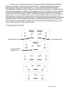
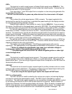
TACH
POWER
GROUND
WARN
DIM (+)
SPD +
SPD SND
SPD -
SPD OUT
SW2 (-)
SW1 (-)
ADJ SND
ADJ -
WTR SND
WTR -
OIL +
OIL SND
OIL -
FUEL +
FUEL SND
FUEL -
WAIT (+)
CRUISE (-)
GEAR (1 WIRE)
4x4 (-)
RIGHT (+)
LEFT (+)
HIGH (+)
BRAKE (-)
CHECK ENG (-)
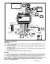
SERIES III
VFD CONTROL BOX
RIBBON CABLE
AUX.
I/O
DISPLAY
STRIPE
www.dakotadigital.com
techsupport@dakotadigital.com
605-332-6513
MOMENTARY
S
W2
MOMENTARY
S
W
1
RIBBON CABLE
DISPLAY PANEL
STATUS LED
DIM-1
Optional
Cruise Control
Engage Output
Glow Plug Relay
or
Wait to start output
ECU/ECM
check engine
output
BIM
CONNECTION
ONLY!
4x4
transfer case
switch
DAKOTA DIGITAL
GSS UNIT
1-Wire output
RIGHT TURN
SIGNAL WIRE
Optional
LEFT TURN
SIGNAL WIRE
HIGH BEAM
WIRE
PARKING BRAKE
SWITCH
SPEED OUT
(2k or 4k PPM)
Connect to tail light circuit
dash will dim when termianl has +12V
Light or Buzzer
(4 Watts or more)
Tail Light
Light or Buzzer
(4 Watts or less)
Relay
EXSISTING
FUEL LEVEL
SENSOR
RED
WHITE
BLACK
Additional ground wire to fuel
sensor body or mounting screw.
PRESSURE SENSOR
SEN-03-8
0-100 PSI
TEMP SENSOR
SEN-04-5
100-300 F
PU
L
SE
GENERATOR
ECU/ECM
Speed Output
RED
WHITE
BLACK
+12V
KEY ON POWER
(fused 5 - 20 AMP max)
Connect to main
chassis ground
Ignition Coil
(negative side)
- +
ECU/ECM
or Ignition Box
(tach output)
SPEED SENSOR
SEN-01-5
16k PPM
BLUE or RED
BROWN or BLACK
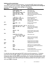
TERMINAL DESCRIPTIONS
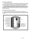
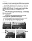
Status LED
This LED is located at the corner of the control box, next to the GROUND terminal. The
LED is used for diagnostics.
• A steady flash, on and off, about one second apart indicates the system is powered and
operating normally.
• On steady indicates low power, below 9V, at the POWER terminal (the displays will also
generally be dim) .
• Not flashing or lighting indicates loss of power or ground.
GROUND
This is the main ground for the display system. A wire should be run from this terminal to
the vehicle’s main chassis ground. Use 18 AWG or larger wire to ensure sufficient groun
ding.
Proper vehicle grounding is extremely important for any gauges (or electronics) to
operate correctly. The engine block should have heavy ground cables to the battery, frame, and
firewall. Failure to properly ground the engine block or the control box can cause
incorrect or erratic operation.