


MAN 650066:D
16
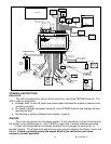
Setting up the control box
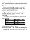
Below is a list of all of the setup menus. You must have SW1 wired to enter setup;
descriptions of each menu are below. Pay close attention to Setup Menus and settings as
incorrect settings will cause faulty readings on the displays.
Main Menu Sub Menu Description____________________
SPEED
SPEEDSPEED
SPEED
SENDER (normal, bus)
SENDER (normal, bus)SENDER (normal, bus)
SENDER (normal, bus)
Select sensor type
AUTO
AUTOAUTO
AUTO (MPH/KMH
MPH/KMHMPH/KMH
MPH/KMH) Auto calibrate speed
ADJUST
ADJUSTADJUST
ADJUST(MPH/KMH,
MPH/KMH,MPH/KMH,
MPH/KMH, normal, bus
normal, busnormal, bus
normal, bus) Adjust the speed calibration
S
SS
Servic
ervicervic
ervic(OFF, 500
OFF, 500 OFF, 500
OFF, 500 –
––
– 7500
7500 7500
7500) Select the service countdown
OUTPUT (2k ppm, 4k PPm)
OUTPUT (2k ppm, 4k PPm)OUTPUT (2k ppm, 4k PPm)
OUTPUT (2k ppm, 4k PPm)
Select output speed signal PPM setting
DONE
DONEDONE
DONE
Exit setup menu
Tach
TachTach
Tach
T CAL (
T CAL (T CAL (
T CAL (Bus,
,,
,1
1 1
1 –
––
– 16)
16) 16)
16)
Set engine cylinder count
UPDATE (
UPDATE (UPDATE (
UPDATE (slow, mid, fast
slow, mid, fastslow, mid, fast
slow, mid, fast)
))
)
Set rpm update rate
WARN (2200
WARN (2200 WARN (2200
WARN (2200 –
––
– 14800)
14800) 14800)
14800)
Set rpm shift warning point
SIGNAL (5 LO, 12 HI)
SIGNAL (5 LO, 12 HI)SIGNAL (5 LO, 12 HI)
SIGNAL (5 LO, 12 HI)
Select rpm signal voltage level
DONE
DONEDONE
DONE
Exit setup menu
VOLT
VOLTVOLT
VOLT
WARN (10.0
WARN (10.0 WARN (10.0
WARN (10.0 –
––
– 13.1)
13.1) 13.1)
13.1)
Set low volt warning point
DONE
DONEDONE
DONE
Exit setup menu
WATER
WATERWATER
WATER
SENDER (
SENDER (SENDER (
SENDER (DD F,DD
DD F,DD DD F,DD
DD F,DD C,
C,C,
C,BUS F, BUS C)
BUS F, BUS C)BUS F, BUS C)
BUS F, BUS C)
Select sensor type
WARN (150
WARN (150WARN (150
WARN (150-
--
-300F
300F300F
300F
/ 65
65 65
65 -
--
-148c)
148c)148c)
148c)
Set high temp warning point
TEST
TESTTEST
TEST
Display sensor ohm reading
DONE
DONEDONE
DONE
Exit setup menu
OIL
OILOIL
OIL
WARN (5
WARN (5 WARN (5
WARN (5 –
––
– 36)
36) 36)
36)
Set low pressure warning point
TEST
TESTTEST
TEST
Display sensor voltage reading
DONE
DONEDONE
DONE
Exit setup menu
FUEL
FUELFUEL
FUEL
SENDER (
SENDER (SENDER (
SENDER (SW 33,
SW 33, SW 33,
SW 33, CUSTOM,
CUSTOM,CUSTOM,
CUSTOM,
Select sensor type
GM 30,
GM 30, GM 30,
GM 30, GM 90, GM 250,
GM 90, GM 250, GM 90, GM 250,
GM 90, GM 250,
F 10, F 150, V 180)
F 10, F 150, V 180)F 10, F 150, V 180)
F 10, F 150, V 180)
CUSTOM
CUSTOMCUSTOM
CUSTOM
Calibrate custom fuel sensor
TEST
TESTTEST
TEST
Display sensor ohm reading
DONE
DONEDONE
DONE
Exit setup menu
PERF
PERF PERF
PERF
O
OO
On
nn
n
Enable performance readings
O
OO
Off
ffff
ff
Disable performance readings
NIGHT
NIGHTNIGHT
NIGHT
Change preset night dimming
BIM
BIMBIM
BIM
SCAN
SCANSCAN
SCAN
Check/scan for connected modules
SETUP
SETUPSETUP
SETUP
Enter setup (only when modules present)
DONE
DONEDONE
DONE
Exit setup menu
INFO
INFOINFO
INFO
SE
SESE
SExx
Current software code
SPEED CAL PPM(
SPEED CAL PPM(SPEED CAL PPM(
SPEED CAL PPM(on press/hold)
Current pulse per mile cal value saved
-
--
-ODOM
ODOMODOM
ODOM
Used to preset odometer miles
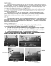
To enter the setup mode, press and hold SW1 while turning the key/power on. The display
should light up and show SE
S
ESE
SET
SETUP
SETUPSETUP
SETUP on the speedometer and speed message displays.
Release the switch and SE
SESE
SET
SPEED
SPEED SPEED
SPEED should display, this is the start of the setup menus. Press
and release switch 1 to advance through the main menus. A press and hold will enter the sub
menu. A press and hold is also used to save the setting and jump to the next option, or exit a
menu when DONE
DONEDONE
DONE is displayed.