


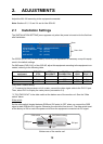

1. MOUNTING, WIRING
11
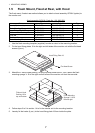
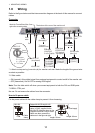
1.8 Wiring
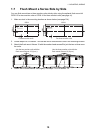
Refer to the figure below and the interconnection diagram at the back of this manual to connect
cables.
Connector
*1: Attach a crimp-on lug (inner dia. φ4) for monitor unit side. Make the length of the ground wire
as short as possible.
*2: Slide switch
• ON (upward): Allow digital signal from external equipment to control on/off of the monitor unit.
• OFF (downward): Set to OFF for analog RGB signal.
Note: Turn the slide switch off when you connect equipment to both the DVI and RGB ports.
*3: BRILL CTRL port
No use. Do not remove the sticker from the connector.
How to fix power cable
Fix the power cable with the cable clamp to prevent it from loosening.
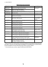
FSV-84/84L
FSV-30/S-BB
FSV-24/S-BB
FCV-30
FCV-1200L/M
FSV-84/84L
FSV-30/S-BB
FSV-24/S-BB
FCV-30
FCV-1200L/M
FAR-21x7
FEA-2107
FCR-21x7
FAR-21x7
FEA-2107
FCR-21x7
FEA-2107
FCR-21x7
FEA-2107
FCR-21x7
The bottom of the rear of the monitor unit
RGB signal
3COX-2P-6C
5 m/10 m (option)
RGB signal
3COX-2P-6C
5 m/10 m (option)
RGB signal
3COX-2P-6C
5 m/10 m (option)
Digital signal
DVI-D/D S-LINK
5 m (standard)/
10 m (option)
Digital signal
DVI-D/D S-LINK
5 m (standard)/
10 m (option)
Digital signal
DVI-D/D S-LINK
5 m (standard)/
10 m (option)
Composite
signal cable
Composite
signal cable
Composite
signal cable
CCD camera
DVD recorder
CCD camera
DVD recorder
CCD camera
DVD recorder
BRILL CTRL
port *
3
BRILL CTRL
port *
3
BRILL CTRL
port *
3
IV-8 sq
(local supply)
*
1
IV-8 sq
(local supply) *
1
IV-8 sq
(local supply) *
1
To ground
terminal on hull
DPYC-1.5
(or equivalent)
DPYC-1.5
(or equivalent)
DPYC-1.5
(or equivalent)
100-230 VAC
Slide
switch *
2
Slide
switch *
2
Slide
switch *
2
Power
switch
Fuse
RS-232C cable
(Max. 10 m)
RS-232C cable
(Max. 10 m)
RS-232C cable
(Max. 10 m)
DPYC-1.5
φ = 11.7 mm
Armor
Sheath
Conductor
S = 1.5 mm
2
φ = 1.56 mm
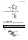
Attach the Terminal Board Gear Cover
again after connecting cables.
MU-190
Cable
clamp
Length: 40 mm
Length: 60 mm
Local supply
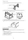
Replace MU-201CE with MU-190
Cut the connector of the power
cable (15-565, supplied on the
MU-201CE). Attach a crimp-on lug
(supplied on the MU-190) to each
cable core then connect the
cables as in the figure at right.