


12
2. ADJUSTMENTS
Adjust the MU-190 according to the equipment connected.
Note: Sections 2.2, 2.3 and 2.4 are for Non-SOLAS.
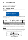
2.1 Installation Settings
The [INSTALLATION SETTING] menu appears only when the power is turned on for the first time
after installation.
For ECDIS (FEA-2107) or chart radar (FCR-21x7), no adjustment is necessary. Keep this equip-
ment in the default settings.
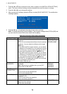
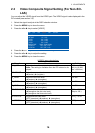
For IMO radar (FAR-21x7) or Non-SOLAS, adjust this equipment according to the equipment con-
nected, referring to the following table.
Gray items: Default setting
*1: To connect to the processor unit of a radar, connect the video signal cable to the DVI-D1 port.
Then, select DVI1 to display the radar picture (see section 3.4).
*2: "DVI PWR SYNC" is the slide switch at the bottom rear of the monitor unit. See the “Slide
switch” below.
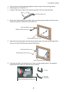
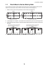
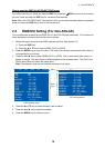
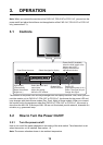
Slide switch
Set the slide switch (located between RGB and DVI ports) to OFF when you connect the RGB
signal or both RGB and DVI signals. Otherwise, the monitor will not turn on. The slide switch is set
at the factory to ON to control the power on/off from the equipment connected via DVI signal.
Bottom rear of the monitor unit
Connected
equipment
EXT BRILL
CTRL
SERIAL
BAUDRATE
COLOR
CALIBRATION
KEY
LOCK
DVI PWR
SYNC *2
FEA-2107, FCR-21x7 RS-232C 9600 ON ON ON
FAR-21x7 DVI *1 - OFF ON ON
Other OFF - OFF OFF OFF
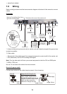
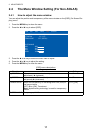
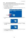
INSTALLATION SETTING
EXT BRILL CTRL
SERIAL BAUDRATE
COLOR CALIBRATION
KEY LOCK
SAVE AND EXIT
RS-232C
9600bps
ON
ON
YES
(OFF/DVI1/DVI2/RS-232C/RS-485/USB)
(4800/9600/19200/38400)
(OFF/ON)
(OFF/ON)
(NO/YES)
Menu
Menu item
Slide switch ON (Default setting)
䋨Ꮏ႐⩄ᤨ䈱⁁ᘒ䋩
Slide switch
ON (Default setting)
DVI port
OFF
RGB port