1
KW-AVX726/KW-AVX725/
KW-AVX626/KW-AVX625
Installation/Connection Manual
JVC
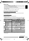
Parts list for installation and connection
If any item is missing, consult your JVC car audio dealer immediately.
12 V
JVC .
•
–
–
–
•
•
•
• Parking Brake
–
•
• JVC
•
50 W 4 – 8
50 W <Amplifier Gain> (
18
)
•
•
ENGLISH
This unit is designed to operate on 12 V DC, NEGATIVE ground electrical systems. If your vehicle does
not have this system, a voltage inverter is required, which can be purchased at JVC car audio dealers.
WARNINGS
• DO NOT install any unit or wire any cable in a location where;
– it may obstruct the steering wheel and gearshift lever operations, as this may result in a traffic accident.
– it may obstruct the operation of safety devices such as air bags, as this may result in a fatal accident.
– it may obstruct visibility.
• DO NOT operate any unit while manipulating the steering wheel, as this may result in a traffic accident.
• The driver must not watch the monitor while driving. It may lead to carelessness and cause an accident.
• If you need to operate the unit while driving, be sure to look around carefully or you may be involved in
a traffic accident.
• If the parking brake is not engaged, “Parking Brake” appears on the monitor, and no playback picture
will be shown.
– This warning appears only when the parking brake wire is connected to the parking brake system built
in the car.
To prevent short circuits, we recommend that you disconnect the battery’s negative terminal and make all
electrical connections before installing the unit.
• Be sure to ground this unit to the car’s chassis again after installation.
Notes on electrical connections:
• Replace the fuse with one of the specified rating. If the fuse blows frequently, consult your JVC car audio
dealer.
• It is recommended to connect speakers with maximum power of more than 50 W (both at the rear and
at the front, with an impedance of 4 to 8 Ω).
If the maximum power is less than 50 W, change <Amplifier Gain> setting to prevent the speakers from
being damaged (see page 18 of the INSTRUCTIONS).
• To prevent short circuits, cover the terminals of the UNUSED leads with insulating tape.
• The heat sink becomes very hot after use. Be careful not to touch it when removing this unit.
Main unit Power cord
Round head screws (M5 × 8 mm)
M5 × 8 mm
Flat head screws (M5 × 8 mm)
M5 × 8 mm
Crimp connector
Remote controller
Batteries
Plate for use with a Nissan car
Heat sink
GET0605-007A
[U/UT]
0109DTSMDTJEIN
EN, CT
© 2009 Victor Company of Japan, Limited
Install1-3_KW-AVX726[UT]2.indd 1Install1-3_KW-AVX726[UT]2.indd 1 08/12/25 17:55:1108/12/25 17:55:11