


26 EuroPak-15a Receiver User Manual Rev 5
Chapter 2 Installation
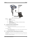
2.2.3 Applying Power to the Receiver
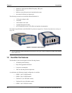
Connect the power supply to the PWR port of the EuroPak-15a receiver.
2.2.4 Connecting Data Communications Equipment
In order to communicate with the receiver by sending commands and obtaining logs, a connection to some
form of data communications equipment is required. The default configuration available for each of the
receiver types is given in the table below. Consult NovAtel Customer Service for more details on factory
configuration. See Appendix A, Technical Specifications starting on Page 110 for data connection details.
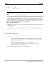
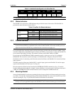
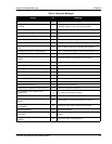
Table 1: Default Serial Port Configurations
Each port supports some, or all, of the following signals:
• Clear To Send (CTS)
• Transmitted Data (TXD)
• Request To Send (RTS)
• Received Data (RXD)
The EuroPak-15a enclosure is Data Terminal Equipment (DTE) so that TXD and RTS are outputs while RXD
and CTS are inputs. A null modem cable is required to connect to another DTE like a terminal or a PC.
2.3 Additional Features and Information
This section contains information on the additional features of the EuroPak-15a receivers, which may affect the
overall design of your receiver system.
2.3.1 Strobes
A set of inputs and outputs that provide status and synchronization signals are given on the EuroPak-15a. These
signals are referred to as strobes. As shown in Table 2 on Page 27, not all strobe signals are provided on all
receivers. However, for those products for which strobes are available, you may want to design your
installation to include support for these signals.
The EuroPak-15a enclosure provides strobe signals at its I/O port, as described in Table 54 on Page 114.
Strobe signals include an input and several outputs as described below:
• Mark Input (Event1) A pulse on this input triggers certain logs to be generated.
(see Section 4.2.2, Log Triggers on Page 34).
• Measure Output (MSR) Falling edge is synchronized with internal GPS
measurements.
• Pulse Per Second Output (PPS) A pulse for which the falling edge is synchronized with GPS
time.
• Position Valid Output (PV) High when good GPS position and time solution.
• Error Output (ERROR) High when a receiver hardware failure is detected.
See Appendix A, Technical Specifications starting on Page 110, for further information on the strobe signal
characteristics.
Receiver COM1 COM2
EuroPak-15a RS-232 RS-232