


Installation Chapter 2
EuroPak-15a Receiver User Manual Rev 5 27
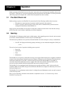
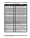
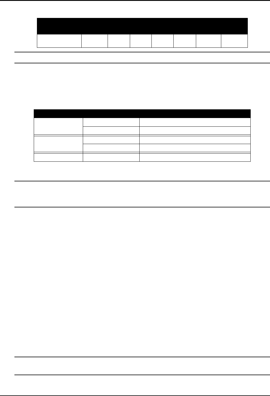
Table 2: Available Strobe Signals on the EuroPak-15a
The ground return pin for these signals is Pin 9.
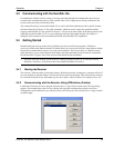
2.3.2 Status Indicators
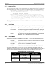
The EuroPak-15a receivers have LED indicators that provide the status of the receiver. The EuroPak-15a
provides the status indicators shown in Table 3.
Table 3: EuroPak-15a Status Indicators
2.3.3 External Oscillator
You may connect an external oscillator to a EuroPak-15a model, without an internal oven-controlled
crystal oscillator (OCXO) as explained in this section. On the EuroPak-15aT model, the OSC port is for
output from the internal OCXO only, and therefore this section does not apply to it.
For certain applications requiring greater precision than what is possible using the on-board 20 MHz, voltage-
controlled, temperature-compensated crystal oscillator (VCTCXO), you may wish to connect the EuroPak-15a
to an external, high-stability oscillator. The external oscillator can be either 5 MHz or 10 MHz.
If you do not use the EXTERNALCLOCK command to specify a clock type, see Page 54, its default is
DISABLED. This means the external clock input is off and the board is using the on-board VCTCXO.
Installation consists of connecting a cable from the external oscillator to the EuroPak-15a’s external oscillator
input connector.
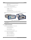
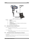
The BNC external oscillator port, labelled OSC, is used for input signals on the EuroPak-15a and for output
signals on the EuroPak-15aT. See Figure 2 on Page 20.
Once the external oscillator has been installed, the EXTERNALCLOCK command, see Page 54, must be
issued to define the clock model (for example, cesium, rubidium or ovenized crystal). If the input clock rate is
5 MHz, the EXTERNALCLOCK command must be issued to change the 10 MHz default rate.
2.3.4 Mounting Bracket
Along with the EuroPak-15a enclosure, mounting kits have been provided to facilitate mounting the receivers
to a surface. To install the mounting bracket provided with the EuroPak-15a, refer to the instructions provided
with the mounting kit. Page 119 provides the dimension information for the bracket.
The mounting kits are not designed for use in high-dynamics/vibration environments. Contact NovAtel,
see Page 14, if your application requires the EuroPak-15a to be mounted in these types of environments.
Signal EVENT1 MSR PPS PV
ERROR
STATUS
_RED
STATUS
_GREEN
EuroPak-15a I/O port,
pin 4
I/O port,
pin 3
I/O port,
pin 2
I/O port,
pin 5
I/O port,
pin 8
Not
available
Not
available
Indicator Indicator Color Status
COM1
Green Data is being transmitted from COM1
Red Data is being received on COM1
COM2
Green Data is being transmitted from COM3
Red Data is being received on COM3
PWR Red The receiver is powered