


63-EN
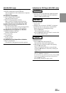
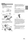
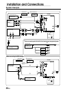
1 Illumination Lead (Orange)
This lead may be connected to the vehicle's instrument
cluster illumination lead. This will allow the backlight-
ing of the IVA-C801/CVA-1006 to dim whenever the
vehicle‘s lights are turned on.
2 Battery Lead (Yellow)
Connect this lead to the positive (+) post of the vehicle's
battery.
3 Fuse Holder (7.5A)
4 Ground Lead (Black)
Connect this lead to a good chassis ground on the ve-
hicle. Make sure the connection is made to bare metal
and is securely fastened using the sheet metal screw
provided.
5 Power Supply Connector
6 Remote Control Interface Connector
Connect to the remote control interface box.
7 Antenna Extension Cable
8 Remote Control Output Lead (White/Brown)
Connect this lead to the remote control input lead. This
lead outputs the controlling signals from the remote
control.
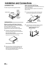
9 Foot Brake Lead
Connect to the vehicle's foot brake lead or brake lamp
lead.
0 Remote Turn-On Lead (Blue/White)
Connect this lead to the remote turn-on lead of your
amplifier or signal processor.
! Power Antenna Lead (Blue)
Connect this lead to the +B terminal of your power
antenna, if applicable.
@ Audio Interrupt In Lead (Pink/Black)
# Parking Brake Lead (Yellow/Blue)
Connect this lead to the power supply side of the park-
ing brake switch to transmit the parking brake status
signals to the IVA-C801/CVA-1006.
$ Switched Power Lead (Ignition) (Red)
Connect this lead to an open terminal on the vehicle's
fuse box or another unused power source which pro-
vides (+) 12V only when the ignition is turned on or in
the accessory position.
% Fuse Holder (15A)
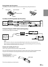
^ Right Front (+) Speaker Output Lead (Gray)
& Right Front (–) Speaker Output Lead (Gray/Black)
* Right Rear (–) Speaker Output Lead (Violet/Black)
( Right Rear (+) Speaker Output Lead (Violet)
) Left Rear (+) Speaker Output Lead (Green)
⁄ Left Rear (–) Speaker Output Lead (Green/Black)
¤ Left Front (–) Speaker Output Lead (White/Black)
‹ Left Front (+) Speaker Output Lead (White)
› System Switch
When connecting an equalizer or divider using Ai-NET
feature, place this switch in the EQ/DIV position. When
no device is connected, leave the switch in the NORM
position.
NOTE
Be sure turn the power off to the unit before changing the
switch position.
fi Remote Output Terminal
fl Antenna Receptacle
‡ I/F (Interface) Lead
° Display Output Terminal
Connect a monitor to this terminal using the I/F lead
(included).