


VRX610 4342 VRX610
11. SPECIFICATIONS
FM Tuner
Frequency Range:
87.9 MHz to 107.9 MHz
Usable Sensitivity:
11 dBf
50dB Quieting Sensitivity:
17 dBf
Alternate Channel Selecitivity:
75 dB
Stereo Separation(1 kHz):
35 dB
Frequency Response(+/-3 dB):
30 Hz to 15 kHz
AM Tuner
Frequency Range:
530 kHz to 1710 kHz
Usable Sensitivity:
25 µV
Audio Amplifier
Rated power output:
17 W × 4 (20 Hz to 20 kHz, 1%, 4 Ω)
Maximum power output: 40 W × 4 (EIAJ)
Speaker impedance: 4 Ω (4 to 8 Ω)
Input/Output
Video input:
1.0 +/- 0.2 Vp-p (input impedance 75 Ω)
Audio output: min.200mVrms
LCD Monitor
Screen Size:
6.5-inch wide type (142 mm Width × 78 mm
Height)
Display method: Transmission type TN liquid
crystal display
Drive method: TFT (thin-film transistor) active
matrix driving
Pixels:
280,800 (1200 × 234)
General
Power source voltage:
14.4 V DC (10.8 to 15.6 V allowable)
Ground:
Negative
Current consumption:
4.0 A (1 W)
Auto Antenna Rated Current:
500 mA less
Dimensions of the Main Unit:
178 (W) × 50 (H) × 157 (D)mm
7(W) × 1-15/16(H) × 6-3/16(D)inches
Weight of the Main Unit:
1.7 kg
Dimensions of the Remote Control Unit:
44 (W) × 110 (H) × 27 (D)mm
1-3/4(W) × 4-5/16(H) × 1-1/16(D)inches
Weight of the Remote Control Unit:
30 g (including battery)
Notes:
• Specifications comply with EIAJ Standards.
• Specifications and design are subject to change
without notice for further immprovement.
1. BEFORE STARTING..................................................43
2. PACKAGE CONTENTS...............................................43
3. GENERAL CAUTIONS................................................44
4. CAUTIONS ON INSTALLATION.................................44
5. INSTALLING THE MAIN UNIT....................................45
6. REMOVING THE MAIN UNIT.........................................47
7. CAUTIONS ON WIRING................................................48
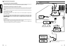
8. WIRE CONNECTION ................................................49
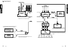
9. SAMPLE SYSTEMS...................................................51
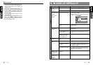
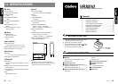
■ Contents
VRX610
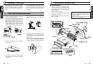
1. This set is exclusively for use in cars with a
negative ground 12 V power supply.
2. Read these instructions carefully.
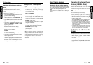
3. Be sure to disconnect the battery “ ” termi-
nal before starting. This is to prevent short
circuits during installation. (Figure 1)
11
11
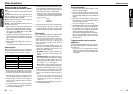
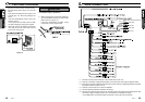
1 Main unit
22
22
2 Manuals
Owner’s manual & Installation manual
Warranty card
33
33
3 Power supply lead
44
44
4
Bag for accessories of the main unit (No. 1)
Flat head screw (M5 × 8)............................4
Sems hexagonal bolt (M5 × 8)....................5
55
55
5
Bag for accessories of the main unit (No. 2)
Hook plate..................................................2
Cord clamp
Spacer
Special screw
66
66
6 Universal mounting bracket
77
77
7 Remote control unit
88
88
8 Battery
(for remote control unit)
99
99
9 Outer Escutcheon
00
00
0 DCP Case
1. BEFORE STARTING
2. PACKAGE CONTENTS
Installation and Wire connection manual