


VRX610 5150 VRX610
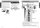
9. SAMPLE SYSTEMS
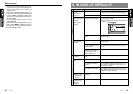
■ Sample System 1
*AMP built-in, line out
4 channel output.
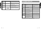
CDC655z/655Tz/1255z
RDC655z/655Tz/1255z
DCZ615/CDZ616
∗ When two CD changers or MD changers are con-
nected, CCA-519 is required.
∗ To enable the correct input, it is necessary to con-
figure the VRX610 as described on page 29.
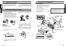
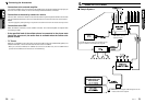
■ Connecting the Accessories
• Connection to the external amplifier
The external amplifier can be connected to the AUDIO 4CH. OUTPUT terminal (RCA pin jack) on
the main unit. In other words, it can be connected provided the DSP is connected.
• Connection to the security camera for vehicle
The rear vision camera for vehicle can be connected to the system expansion terminal on the main
unit. For detailed information, refer to the instruction sheet or manual for the rear vision camera.
Notes:
• A power supply box (sold separately) is required for connection of the main unit and the security camera.
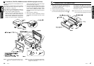
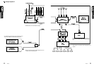
• Connection to the DSP
When the DSP is connected, use the CeNET connector. The external amplifier is required when
connecting the DSP.
• If the specified lead of the cellular phone is connected to the phone mute
lead of the source unit, the audio mute is available when the cellular tele-
phone is used.
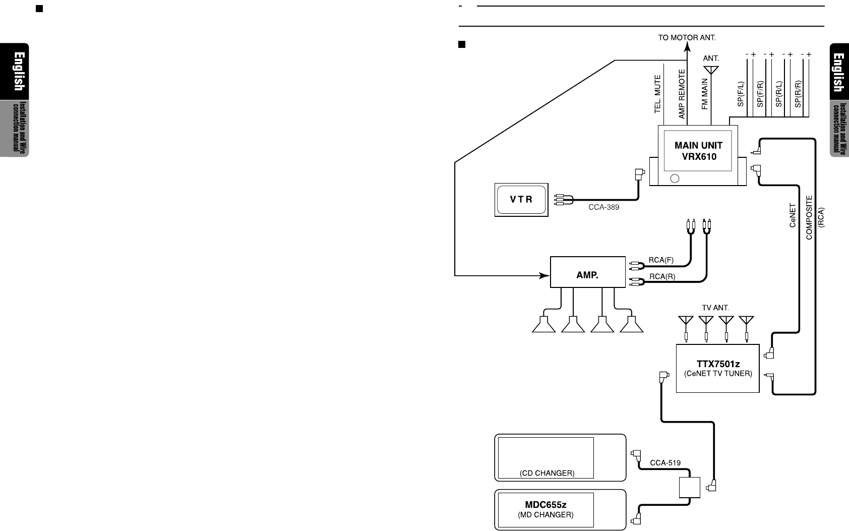
• TV Tunner
When the TV TUNER is to be connected, connect the CeNET connector and RCA PIN (yellow). For
detailed information, refer to the instruction manual of the TV TUNER.
* When you connect the PKB lead TV TUNER, also connect it to the Main unit. (The TV TUNER will not
operate with the PKB lead connected to the TV TUNER only.)