


10
ISP - Rev 6/95
easily replaced in cases when COMP trimmer range is not enough to get optimum
result.
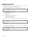
The output of the error amplifier is:
1 + SxC1xR5
Vo = (V
1
G
v1
+ V
2
G
v2
) x [ --------------------------- ]
1 + SxC1xR5(1 + RfxKi/R5)
V
1
,V
2
, - Input signals
G
v1
,G
v2
- Gain of inputs.
Ki = Position factor of the wiper of COMP trimmer.
Full CW = 0.1
Full CCW = 1
The feedback element must be connected for negative feedback.
The polarity of the ISP servo amplifiers is such that a positive input signal
results in a negative voltage at terminal M1 with respect to terminal M2.
4.2.1 Velocity control using armature voltage feedback
By inserting R8 to its solderless terminals, the armature voltage is fed into
the error amplifier to be used as a velocity feedback. This feature is useful for
all cases when low regulation ratio and low speed accuracy are acceptable.
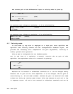
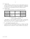
4.3 Current mode
In order to operate the servo amplifier as a current amplifier, the velocity
loop should be disabled. This is done by converting the error amplifier into a
low gain DC amplifier which has a flat response beyond the desired current
bandwidth. In this mode, R6 and C1 have to be removed from the circuit.