


44
ISP - Rev 6/95
9. Tables and Summaries
9.1 Adjusting trimmers
Six trimmers are installed on the ISP board with the following functions:
T7 (Gain 1) - CW rotation increases input 1 gain.
T6 (Gain 2) - CW rotation increases input 2 gain.
T5 (Balance) - see 8.1.
T4 (compensation) - See 8.6.
T3 (Ip) - CW rotation increases peak current limit (see 8.2).
T2 (Ic) - CW rotation increases continuous current limit (see 8.2)
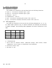
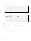
9.2 LED diagnostics
Four LEDs are installed on the ISP with the following designations: Ic, In, Vs,
SO. Under normal operation only Vs should illuminate (Vs indicates the existence
of supply voltages). The following table represents the faults indications of the
LEDs:
1 2 3
Ic X
In X
Vs X X X
SO X
X - Illuminated LED
1. One or more of: external inhibit, under/over voltage, short circuit, excess
temperature, loss of tacho or insufficient load inductance.
2. Continuous current limit.
3. The shunt is "ON".