


38
ISP - Rev 6/95
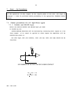
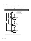
7.1.5 Latch mode of the protective functions
Self Restart(D17 removed): The amplifier is inhibited only for the period that
the inhibit cause is present.
Latch (D17 - inserted): Failures 4.7.1-5 latch the Inhibit and the diagnostic
LED. For restart (after clearing the failure source), reset has to be performed
by connecting the reset input to the circuit common.
7.1.6 Activating the dynamic contouring of the current limits
If you do not use this feature make sure that R11 and R13 are not installed on
the board.
If you want to activate this function refer to appendix B.
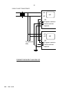
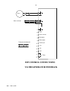
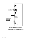
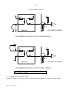
7.2 Velocity control using tachogenerator feedback
When using tacho feedback, it is recommended to use the single ended input no.2
for the tacho signal and to use the differential input for the reference signal
in order to reduce common mode noises.
R2,R3 and R4 are calculated and inserted for two tacho voltage ranges:
For Vtm > 7.5V
R3 = R4 = 1.33xVdm (Kohm)
Vdm - maximum reference voltage at the differential input.
R2 = 2xVtm - 15 (kohm)
Vtm - Voltage generated by the tacho at maximum velocity.
For Vtm < 7.5V
R3 = R4 = 10xVdm/Vtm (Kohm)
Vdm - maximum reference voltage at the differential input.
Vtm - Voltage generated by the tacho at maximum velocity.
R2 = 470 Ohm