


36
ISP - Rev 6/95
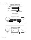
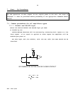
7.1.2 Velocity mode
To operate in velocity mode the velocity loop should be enabled by converting
the error amplifier to a high gain PI amplifier.
Make sure that: R6 (30ohm), R5 (475Kohm) and C1 (0.022 æF), in solderless
terminals, are installed on the board.
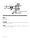
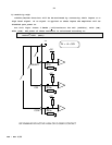
7.1.3 Current mode
a) Converting the amplifier into current mode
To operate in current mode the velocity loop should be disabled by converting
the error amplifier to a low gain proportional amplifier.
- Remove R6 (in solderless terminals).
- Remove C1 (in solderless terminals).
In addition, you must make sure that the velocity feedback signal is not
entering the error amplifier. If a tachogenerator is used, make sure that it is
not connected to the amplifier.
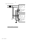
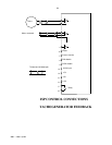
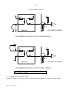
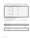
b) Selecting the reference signal gain
The ISP has 2 single ended inputs (terminals H-1,R-32a,E-J1/3 and H-5,R-28a,E-
J1/1) and a differential input (terminals H-3,R-30a,E-J1/4, and H-4,R-30c,E-
J1/5).
The standard procedure recommends to use the differential input for the
reference signal.
Following are the input maximum voltage and impedance with the standard values
of input resistors:
INPUT - RESISTOR STANDARD
VALUE
MAX.
VOLTAGE
Current Gain(A/V)
(in current mode)
INPUT
IMPEDANCE
Input 1 - R1 2.49Kohm 11V 0.46xIc 17.5 Kohm
Input 2 - R2 15Kohm 19V 0.27xIc 30Kohm
Differential - R3,4 20Kohm 30V 0.27xIc 30 Kohm
See chapter 4.1 for calculation of other values