


42
ISP - Rev 6/95
8.5 Response adjustment (velocity mode only)
In most applications optimum response is achieved by adjusting the compensation
(COMP) trimmer. Adjustment procedure is as follows:
- Provide the amplifier with a low frequency, bi-directional square wave velocity
command (A 0.5Hz, ñ2.0V waveform is often employed)
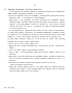
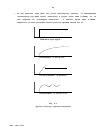
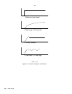
- Apply power to the amplifier, and while monitoring the tachometer signal,
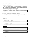
gradually adjust the COMP trimmer from the CCW toward the CW position. Optimum
response (critically-damped) should be achieved at some position before
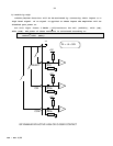
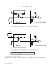
reaching full CW on T4. Fig 8.1 illustrates the types of waveforms observed
for various setting o T4.
In some applications, especially those where the load inertia is much smaller
or larger than normally encountered, the standard compensation components values
of 0.022æF for C1 and 470Kohm for R5 may not allow an optimum setting of the COMP
trimmer T4. In fact, the velocity loop may be unstable for any setting of T4.
In these cases different values for C1 and R5 must be chosen. The following
procedure can be used to select these values:
- Short circuit C1 with a short jumper wire.
- Replace R5 with a decade resistance box. Initially set the box resistance at
20Kohm.
- Set T4, the COMP trimmer to approximately midrange.
- Input a 0.5Hz, ñ2V bi-directional square wave velocity command signal to the
amplifier.
- Apply power, and while monitoring the tachometer signal, gradually increase the
value of the box resistance until optimum response a depicted in Fig 8.1 is
achieved.
- Substitute the closest standard value discrete resistor for R6 and
remove the decade resistance box.
- Remove the shorting jumper across C1, and again check the response using the
squarewave test signal. If near optimum result are obtained, trim the response
using the COMP trimmer T4 for the optimum.