


45
ISP - Rev 6/95
Appendix A - Response adjustment - current loop
In most applications it is not necessary to adjust the current loop to achieve
the optimum response. When there are extreme electrical parameters in the
armature circuit (inductance and resistance) the standard components values of
0.01æF for C2 and 100Kohm for R7 may not yield with the optimum response. The
current loop should be optimized as follows:
- Turn the amplifier to a current amplifier by removing C1 and R6.
- Provide the amplifier with a bi-directional square wave current command (100-
200Hz, ñ2.0V waveform is often employed).
- Apply power to the amplifier, and monitor the load current either by a current
probe or by the current monitor.
If the current response is not critically damped, use the following procedure
- Short circuit C2 with a short jumper wire.
- Replace R7 with a decade resistance box. Initially set the box resistance at
10Kohm.
- Apply the square wave test signal to the amplifier input.
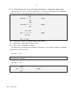
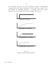
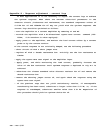
- Apply power, and while monitoring the load current, gradually increase the
value of the box resistance until optimum response a depicted in Fig A-1 is
achieved.
- Substitute the closest standard value discrete resistor for R7 and remove the
decade resistance box.
- Remove the shorting jumper across C2, and again check the response using the
square wave test signal.
- If the previous step does not yield satisfactory results, if unacceptable
overshooting has been noted, substitute a larger value than 0.01 æF; or, if the
response is overdamped, substitute smaller value than 0.01 æF. Repetition of
this procedure should yield an optimum choice for C2.