


40
ISP - Rev 6/95
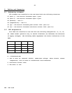
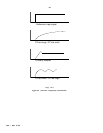
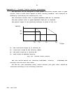
8. Amplifier adjustment and diagnostics
Important remarks:
A. If all the previous steps were accomplished you may now turn on the power and
continue with the following adjustments. You may omit the step for current mode
or velocity mode according to your application.
B. In some applications, especially those where the motor electrical parameters
(total inductance and resistance in the armature circuit) are much smaller or
larger than normally encountered, the current loop response should be optimized
before proceeding with the following steps - See Appendix A.
8.1 Balance adjustment
If the motor is rotating with the command signal at zero voltage, a balance
adjustment will be necessary. Turn the balance trimmer (T5) as required until the
motor stops. As a rule, have the command signal connected and set to zero when
balancing the amplifier. This way, any offset in the command signal will be
canceled.
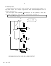
8.2 Current limit adjustment
The amplifiers' current limits can be adjusted without the need for loading.
Disconnect motor leads and connect a voltmeter between the Current Command
Monitor (terminal H-15,R-18a,E-J1/7) and the circuit common. Apply maximum input
voltage to one of the inputs to cause an error at the error amplifier (input gain
trimmer should be fully CW). In order to adjust the continuous limit - turn T3
(Ip) fully CCW to disable Ip, then use T2 (Ic) to adjust the continuous limit by
monitoring the meter readout. Full CW rotation of T2 will result in rated current
limit. After adjusting the continuous limit, turn T3 up to the desired peak
level.
The current monitor range is up to 7.5V and its scale depends on the amplifier
rated continuous current (Ic) and is given by: