


11
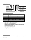
ISP - Rev 6/95
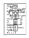
4.4 Current loop
Current loop control is obtained by op amp U1/B (Current amplifier) and R7, C2
which form a lag-lead network for current loop. The standard amp is equipped with
R7 (100Kohm) and C2 (0.01æF) to get optimum current response for an average motor
in this power range. These components are mounted in solderless terminals.
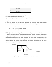
4.5 Current limits
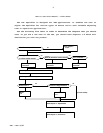
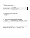
The servo amplifier can operate in the following voltage-current plane:
-Ip -Ic
+V
Ic Ip
Intermittent
zone
Continuous
zone -V
Ic - Continuous current Ip - Peak current
Fig. 4.1: Voltage-Current plane
Each amplifier is factory calibrated to have this shape of voltage-current
operating area with rated values of continuous and peak current limits. In
addition the peak current limit is time dependent as explained in 4.5.1.
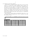
4.5.1 Time dependent peak current limit
The peak current is so designed that its duration is a function of the peak
amplitude and the motor actual operating current before the peak demand. The
maximum peak current is available for 1.6 second. The duration of Ip is given by: