


39
ISP - Rev 6/95
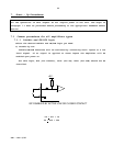
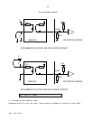
7.3 Velocity control using armature voltage feedback
The reference signal should be connected to the differential input and R3,R4
should be calculated and inserted according to:
R3 = R4 = 1.33xVdm (Kohm)
Vdm - maximum reference voltage at the differential input.
The armature voltage feedback will enter the error amplifier by inserting R8,
calculated for the two voltage types as follows:
For ISP-X/65:
R8
(65V)
= 1.3xVam (Kohm)
Vam - armature voltage at maximum application speed
For ISP-X/135:
R8
(135V)
= 0.73xVam (Kohm)
Vam - armature voltage at maximum application speed
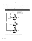
IxR compensation
In order to improve the speed stability in various load conditions, an IxR
compensation is required. This is achieved by:
- Connect the Current Feedback Monitor (terminal H-7,R-26a,E-J1/6) to input 1
(terminal H-1,R-32a,E-J1/3).
- Rotate T7 to max. CCW position (minimum IxR compensation).
- Insert R1 as follows:
3 x Vam
R1 = ---------- (Kohm)
Rm x Ip
Vam - Armature voltage at maximum application speed.
Ip - Amplifiers' rated peak current limit.
Rm - Total ohmic resistance of motor.