


24
ISP - Rev 6/95
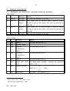
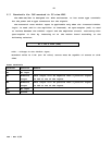
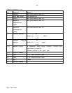
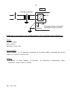
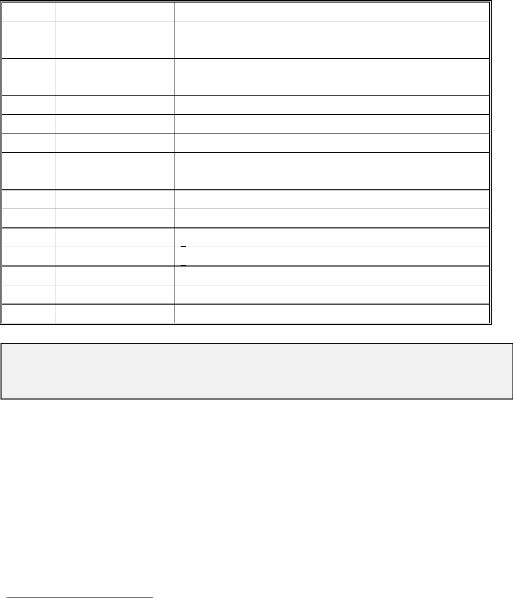
Control connector - J2
Pin Function Remark
1 Inhibit input Potential free inhibit input (-).
See 7.1.1 *
2 Inhibit input Potential free inhibit input (+).
See 7.1.1 *
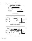
3 Inhibit input Two modes - see chapter 7.1.1 *
4 CCW disable Two modes - see chapter 7.1.1 *
5 CW disable Two modes - see chapter 7.1.1 *
6 Reset for latch
mode
low level input voltage
*
*
*
enables the amplifier
(see 7.1.5).
7 Back EMF output See Appendix B.
8 Input 2 For more details see 4.1.
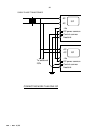
9 -15V + 5%, 50mA external load.
10 +15V + 5%, 50mA external load.
11,12 Circuit common
13 +5V 100mA
14,15 Circuit common
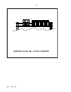
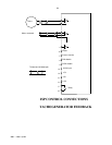
Remark: In the following paragraphs the terminals will be related to all the
mounting types as in the the following example:
H-18,R-16c,E-J1/8.
*
*
*
-1V < Vil < 1V ; 2V < Vih < 30V
Source sink capability - 2mA.