


Installing the Equipment
EN/LZT 790 0003/2 R1A
2-2
2.7.9 Alarm Connector and Relay ............................................................... 2-15
2.7.10 RS-232 Low-speed Asynchronous Data Output ................................ 2-15
2.7.11 Serial Remote Control........................................................................ 2-16
2.8 Option Card Connectors..................................................................... 2-16
List of Figures
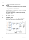
Figure 2.1
Air-flow Through the Equipment........................................................... 2-5
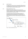
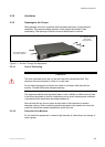
Figure 2.2 AC Power Inlet Assembly..................................................................... 2-7
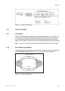
Figure 2.3 Location of the Technical Earth............................................................ 2-9
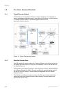
Figure 2.4 Typical Receiver Rear Panel................................................................ 2-9
Figure 2.5 Signal Connections ............................................................................ 2-10
List of Tables
Table 2.1
Supply Cord Wiring Colors................................................................... 2-7
Table 2.2 Non Standard Supply Cord Wire Colors............................................... 2-8
Table 2.3 Digital Output Connector.................................................................... 2-11
Table 2.4 Digital Output Connector.................................................................... 2-11
Table 2.5 Analogue/Digital Audio Connectors.................................................... 2-12
Table 2.6 Digital (Unbalanced) Audio Connectors ............................................. 2-12
Table 2.7 SVGA Connector................................................................................ 2-13
Table 2.8 Frame Sync Hi-Z Connector............................................................... 2-14
Table 2.9 Ethernet Pin-outs ............................................................................... 2-14
Table 2.10 Digital Input Connector....................................................................... 2-14
Table 2.11 Alarm Connector ................................................................................ 2-15
Table 2.12 RS-232 Low-speed Data.................................................................... 2-15
Table 2.13 RS232/RS485 Remote Control .......................................................... 2-16