


F940GOT Handy Series Installation 3
3-5
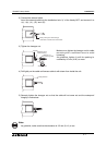
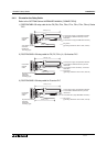
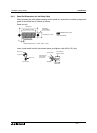
Note 1:
These are signals for communication with the PLC. When connecting to a port other than
the programming port of the FX, A, QnA or Q series PLC, refer to the manual of the
connected module. Also use a relay cable. For relay cable details, refer to section 1.3.2.
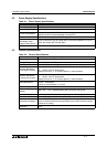
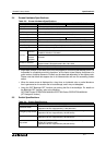
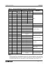
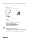
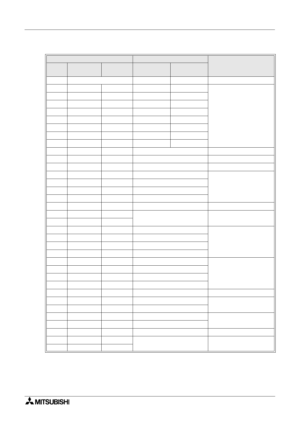
Table 3.1: Name of communication lines, power supply and switches
External Cable (F9GT-RHCAB-*M) Signal Name
Description
Pin No. Color of wire
Arrangement
of color
F940GOT Handy
(RS422)
F943GOT Handy
(RS232C)
1 Shield FG (shield) Frame ground
2 Yellow/Blue a) TXD+ (SDA) SD (TXD)
Note 1
3 Yellow/Red a) TXD- (SDB) ER (DTR)
4 White/Blue a) RTS+ (RSA) RD (RXD)
5 White/Red a) RTS- (RSB) DR (DSR)
6 Gray/Blue a) RXD+ (RDA) RS (RTS)
7 Gray/Red a) RXD- (RDB) CS (CTS)
8 Orange/Blue a) CTS+ (CSA) NC
9 Orange/Red a) CTS- (CSB) NC
10 Orange/Red c) SG Signal ground
11
−−
NC Not used
12 White/Red b) SW-COM
COM for Operation switches
13 Gray/Blue b) SW1
Operation switches
14 Gray/Red b) SW2
15 Orange/Blue b) SW3
16 Orange/Red b) SW4
17
−−
NC Not used
18 Gray/Blue d)
DC24V G
24V DC power supply
"
-
"
19 Gray/Red d)
20 Pink/Red d) ES1-1
Emergency stop switch
21 Pink/Blue d) ES1-1
22 Orange/Red e) ES1-2
23 Orange/Blue e) ES1-2
24 White/Red d) DSW-1
Grip switch
25 White/Blue d) DSW-1
26 Yellow/Red d) DSW-2
27 Yellow/Blue d) DSW-2
28 White/Blue b) KSW-C Common for keylock switch
29 Yellow/Red b) KSW-1
Keylock switch
30 Yellow/Blue b) KSW-2
31 Pink/Red b) Spare SW
Spare
32 Pink/Blue b) Spare SW
33,34,35
−−
NC Not used
36 Orange/Blue d)
DC 24V+
24V DC power supply
"
+
"
37 Orange/Red d)