


F940GOT Handy Series Installation 3
3-9
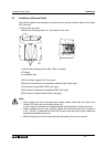
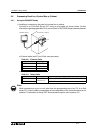
3.4 Processing Panel for a Control Box or Cabinet
3.4.1 Using the F940GOT Handy
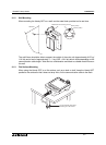
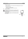
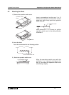
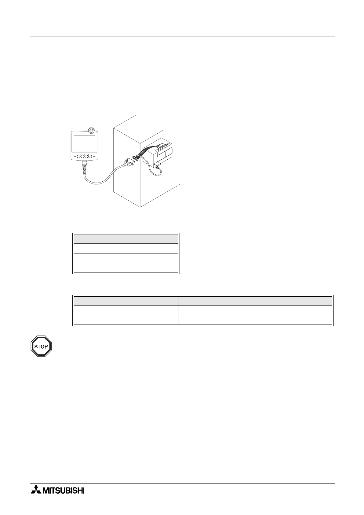
1) Installing a connector on the panel of a control box or cabinet.
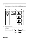
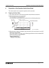
Connect to an FX/A/QnA Series PLC using a relay cable as shown below. Further
information regarding applicable PLCs can be found in GOT-F900 Series Hardware Manual.
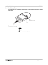
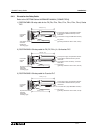
a) External cable (with 37-pin D-Sub, male connector)
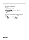
b) Relay cable for connection to PLC
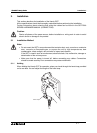
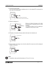
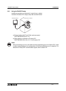
Note:
When connecting to a port or unit other than the programming port of an FX, A or QnA
series PLC, make a cable corresponding to the configuration of the communications port in
question. For allocation of Handy GOT communication signals, refer to section 3.2.
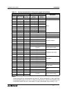
Table 3.2: External Cable
Model Name Length
F9GT-RHCAB-3M 3m (9' 10")
F9GT-RHCAB-6M 6m (19' 10")
F9GT-RHCAB-10M 10m (32' 9")
Table 3.3: Relay Cable
Model Name Length Applicable
F9GT-RHCAB2-150
1.5m (4' 11")
FX Series (FX
0
, FX
0S
, FX
0N
, FX
1S
, FX
1N
, FX
2N
, FX
2NC
)
F9GT-RHCAB3-150 FX (FX, FX
2C
), A, QnA Series
POWER GRIP SW
a )
b )
P L C
F 9 4 0 G O T H a n d y
C o n t r o l b o x o r c a b i n e t