


F940GOT Handy Series Installation 3
3-6
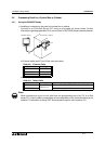
3.3 Installation of External Cable
This section explains the installation procedure for the optional external cable to the Handy
GOT main unit.
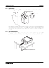
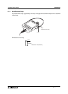
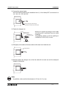
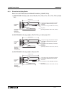
1) Remove the rear cover
Remove the mounting screws "a)", and open the rear cover.
a) Rear cover mounting screws, (M3
×
8mm, 4 screws)
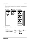
b) Packing
c) Installation hole
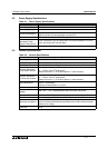
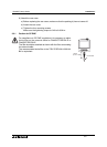
(A)Port for power supply (CN1; 8-pin type)
(B)Port for communication and operation switches (CN2; 20-pin type)
(C)Connector for grip switch (CN4; 5-pin type)
(D)Connector for emergency stop switch (CN5; 4-pin type)
(E)Connector for keylock switch (CN6; 3-pin type)
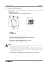
Note:
• Never remove any screw (among seven screws located around the rear face of the
Handy GOT) other than the mounting screws "a)".
If such a screw is removed, the waterproof ability may deteriorate or failure may occur.
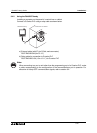
• When installing the rear cover, securely tighten the mounting screws with a torque of
0.49 ~ 0.68 N
m. If tightened more than this, the rear cover may crack, and the water and
dustproof proprieties may be lost.
• Before closing the rear cover, make sure that the packing "b)" has not come off.
a )
N o t e
b )
c )
( A )
( B )
( C )
( E )
( D )