


F940GOT Handy Series Maintenance and Diagnostics 5
5-3
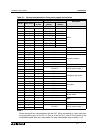
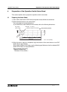
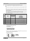
5.2.2 When an operation switch or emergency stop switch does not operate
When an operation switch or emergency stop switch does not operate, check the following
points.
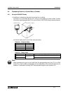
• Check whether external cables are connected correctly to the Handy GOT. (Refer to chapter
3)
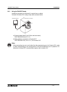
• While pressing and holding an operation switch or emergency stop switch, check the
conduction between the wires (pins or terminal blocks) of the external cables and relay
cable in the table below.
If no conduction is confirmed, wire breakage or poor contact may be present in the external
cable or relay cable, or the circuits inside the Handy GOT may be damaged.
If it is suspected that the circuits inside the Handy GOT are damaged, consult with a
Mitsubishi Electric distributor.
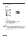
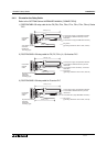
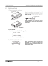
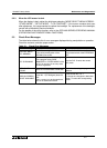
*1 Connect an external cable to the Handy GOT, press and hold each switch, then check
the conduction between the pins or wires.
F9GT-HCAB-
M
37-pin D-sub, male connector
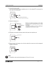
*2 Connect an external cable and relay cable to the Handy GOT, press and hold each
switch, then check the conduction between wires.
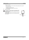
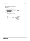
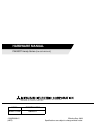
*3 Arrangement of color type.
Switch
name
Signals whose conductivity can be checked
Signal
name
External cable
*1
External cable F9GT-HCAB-
M
+
Relay cable
*2
F9GT-HCAB2-150
F9GT-HCAB3-150
F9GT-HCAB5-150
F9GT-HCAB-3M
F9GT-HCAB-10M
SW1 SW-COM and SW1
12 and 13 White/Red and Gray/Blue (B)
*3
SW2 SW-COM and SW2
12 and 14 White/Red and Gray/Red (B)
*3
SW3 SW-COM and SW3
12 and 15 White/Red and Orange/Blue (B)
*3
SW3 SW-COM and SW4
12 and 16 White/Red and Orange/Red (B)
*3
ES1-1 ES1-1 and ES1-1
20 and 21 Pink/Red and Pink/Blue (D)
*3
ES1-2 ES1-2 and ES1-2
22 and 23 Orange/Red and Orange/Blue (D)
*3
KSW-1 KSW-COM and KSW-1
28 and 29 White/Blue and Yellow/Red (B)
*3
KSW-2 KSW-COM and KSW-2
28 and 30 White/Blue and Yellow/Blue (B)
*3
119
20
37
{
/
{
{
/
{
{
/
{
{
/
{
{
/
{
Arrangement of color (Color type)
Type A Type B Type C
Type D Type E