


ENGLISH
FRANÇAISDEUTSCHEESPAÑOLITALIANO
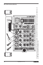
XP150 Mixer Layout
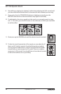
7. REVERB Switch – Use the REVERB switch to add an eect to a Mic or Line input on
any of the inputs 1–3. The REVERB LED indicator lights GREEN when the REVERB is
ON.
8. REVERB Indicator –The REVERB LED will illuminate when the REVERB switch is
pressed down, indicating the channel is set to add reverb (see #7 above).
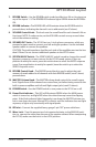
9. VOLUME Control Knob – This knob sets the overall level for each channel’s Mic or
Line input. NOTE: To reduce noise, set the VOLUME controls on any unused chan-
nels to the minimum setting.
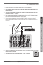
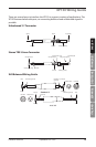
10. SPEAKER OUT Jacks – The XP150 has two ¼-inch phone connectors, which are
powered outputs used to connect your left and right speakers. Use the included
speaker cables to connect the speakers.
CAUTION: The total impedance load for each side of the amplier must not be less
than 8 Ohms. Do not connect additional speakers to the XP150 mixer.
11. SPEECH/MUSIC Switch – The SPEECH/MUSIC switch is used to change the overall
frequency response, or tone contour, for the XP150 sound system. If your ap-
plication is mainly for music, press the switch down to select the MUSIC response
curve. If your application is mainly for speech, leave the switch up to select the
SPEECH response curve.
12. REVERB Control Knob – The REVERB control knob is used to adjust the total
amount of reverb added to all channels with their REVERB switch (see #7 above)
pressed down.
13. MASTER Volume Knob – The MASTER volume knob controls the overall output
level. Signals from all ve channels are routed here just before being routed to the
built-in power ampliers and Left and Right output jacks (see #10 above).
14. POWER Switch – Use the POWER switch to turn power to the XP150 on or o.
15. Power/Peak Indicator – This LED will illuminate GREEN when the MAIN power
switch is turned on, and light RED when the when the amp is near the clipping
point. If the Peak indicator lights frequently, turn down the MASTER volume con-
trol or turn down the input channel VOL controls, until the indicator does not light
anymore, or lights only occasionally with signal peaks.
16. IEC Inlet – Connect the supplied heavy-gauge 3-pin “IEC” power cable here.
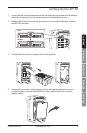
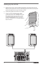
17. Mixer Lock – Turn this quarter turn lock counterclockwise, to the RELEASE poisi-
tion, to remove the mixer from the rear of the speaker cabinet. When transporting
the XP150, make sure the lock is in the LOCK position.
Owner's Manual
13
Expedition XP150