


. . . . . . . . . . . . . . . . . . . . . . . . . . . . . . . . . . . . . . . . . . . . . . . . . . . . . . . . . . . . . . . Wiring and Power
9176/D173 D
ISK SUBSYSTEM - SITE PREPARATION GUIDE 21
S
IXTH EDITION
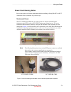
Power Cord Routing Notes
Review this power cord routing information before installing a StorageTek 9176 or D173
rackmount device (controller tray or drive tray).
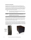
Rackmount Power
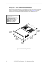
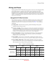
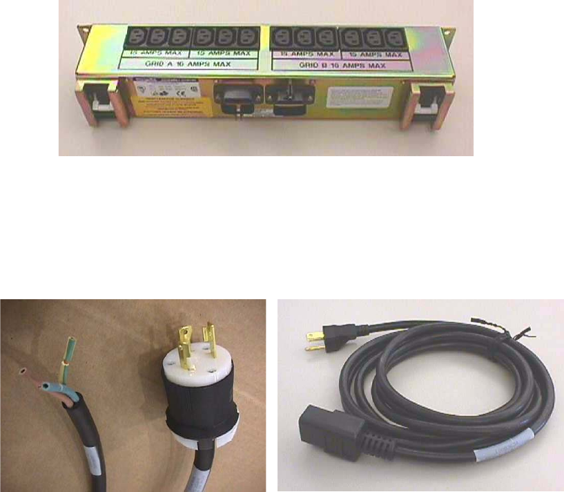
The D173 rackmount cabinet has two power grids in a caboose-mounted power
distribution unit (PDU); and the 9176 (M03) rackmount cabinet has two AC power
distribution units mounted vertically along the side members. Each separate grid (see
photograph, Figure 4) or PDU enables power redundancy to the Disk Subsystem hardware
components, ensuring ongoing data access in the event of a power failure to one of the
customer-supplied circuits (assuming two separate power sources/circuits).
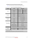
Figure 4 D173 PDU for distributing Power to Devices throughout the Cabinet
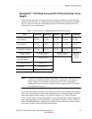
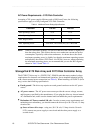
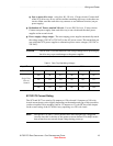
NOTE The following illustrations show various PDU power connectors available
that attach to the customer-supplied power receptacles.
The customer’s power source should come from separate and isolated
power circuits to maximize power redundancy and optimize the Disk
Subsystem data availability.
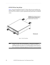
Figure 5 Power Connector types that attach to the customer-supplied power receptacle
9176 POWER CORDS
D173 POWER CORD