


. . . . . . . . . . . . . . . . . . . . . . . . . . . . . . . . . . . . . . . . . . . . . . . . . . . . . . . . . . . . . . . . . . . . . . . . . . . . . .
30 9176/D173 D
ISK SUBSYSTEM - SITE PREPARATION GUIDE
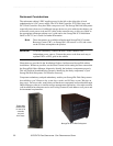
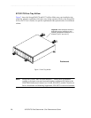
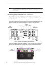
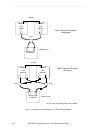
NOTE The photograph below shows the D173’s host (two per subsystem or one
redundant connection) and drive interface connectors (which support up to 30
drive modules).
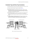
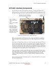
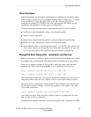
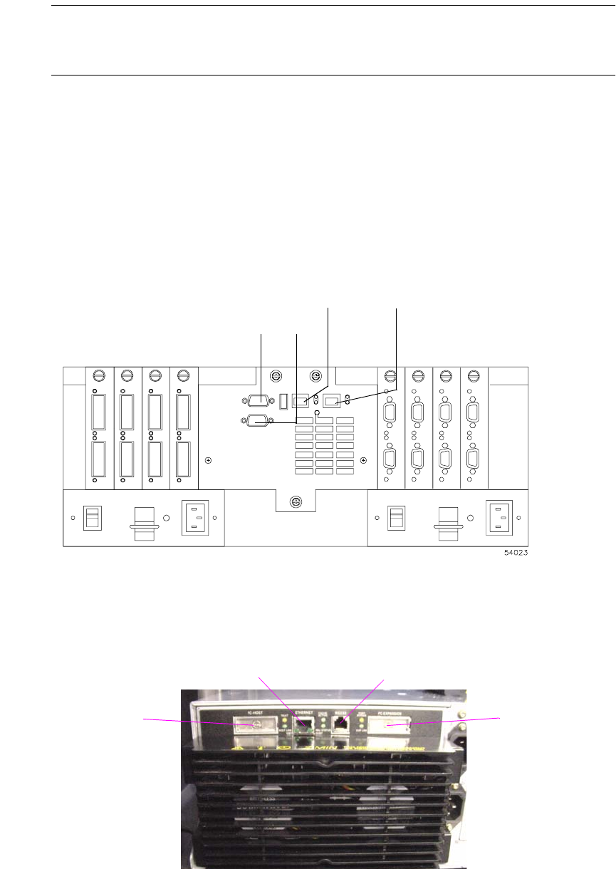
Secondary (Diagnostic) Interface Connectors
The controller tray provides an RS-232 (serial) and an Ethernet connection to each
controller (Controller A and Controller B) for use in diagnostics, troubleshooting, and
special configurations.
If you plan to manage the storage arrays directly from a remote management station, you
must do so through direct Ethernet connections to Controller A and Controller B.
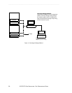
Figure 11 Controller Tray Diagnostic Interface Connectors
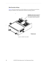
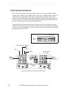
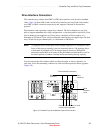
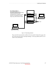
These same diagnostic connections are on the D173 Disk Controller Array, as shown in
this back view photograph of one redundant side’s controller module and fan module.
RS-232
Ctlr A Ctlr B
Ethernet
Ctlr B Ctlr A
HOST
INTERFACE
DRIVE
INTERFACE
ETHERNET
RS 232
HOST
INTERFACE
DRIVE
INTERFACE