


. . . . . . . . . . . . . . . . . . . . . . . . . . . . . . . . . . . . . . . . . . . Controller Tray and Drive Tray Connectors
9176/D173 D
ISK SUBSYSTEM - SITE PREPARATION GUIDE 29
S
IXTH EDITION
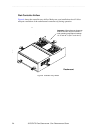
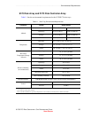
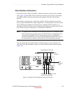
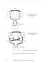
Drive Interface Connectors
The controller tray contains four GBIC or DB-9 host interface cards aka drive minihub
cards. Figure 10 shows DB-9 cards in each drive interface card slot. Each card contains
two GBIC or DB-9 connectors respectively and supports 8-bit and 16-bit interface
protocol.
Each interface card represents a single drive channel. The drive channels are set up in
pairs to support redundant drive loop configurations, or two data paths to each drive. Each
pair of channels can support up to 10 drive trays, containing 10 drives apiece, or a
maximum of 100 drives. Thus, a fully configured controller tray can support up to 20 drive
trays (10 drive trays per channel pair), or a maximum of 200 drives.
NOTE 72 gigabyte drives would equal a total storage capacity of 14.4 terabytes. Note:
Some of this storage capacity is used to format the drives. 180 gigabyte drives
would equal 36 terabytes of 9176 storage capacity; however, StorageTek
encourages individuals to be aware of the performance requirements as well as
the time required to conduct a backup before maximizing storage capacity.
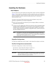
You can connect the drive channel cables to either the upper or lower connectors on
each card. Leave the remaining connector on each card unoccupied for future upgrades
(Figure 10).
Figure 10 Controller Tray Drive Minihub Cards and Connectors
012
3
Drive Interface Connectors
Drive
Channel 1
Drive
Channel 1
Reserve one connector on each
card for future upgrades.
DB-9
Interface
Card