


. . . . . . . . . . . . . . . . . . . . . . . . . . . . . . . . . . . . . . . . . . . Controller Tray and Drive Tray Connectors
9176/D173 D
ISK SUBSYSTEM - SITE PREPARATION GUIDE 27
S
IXTH EDITION
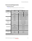
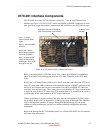
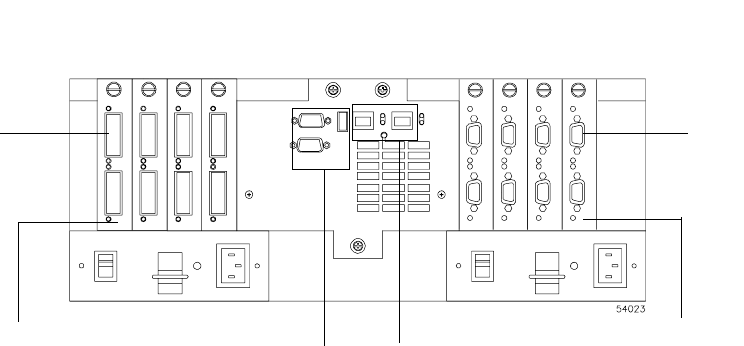
Controller Tray and Drive Tray Connectors
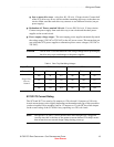
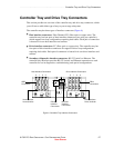
This section provides an overview of the controller tray and drive tray connectors, which
you will use to cable either type of tray to your storage subsystem.
The controller tray has three types of interface connectors (Figure 8).
•
Host interface connectors: Fiber Channel (FC) (fiber optic or copper wire). The
controller tray has four pairs of host interface connectors (two pairs per controller),
which support host loop configurations requiring dual cables. Each pair of connectors
is housed in it own host interface card canister.
•
Drive interface connectors: FC (fiber optic or copper wire). The controller tray has
four pairs of drive interface connectors for support of drive loop configurations
requiring dual cables. Each pair of connectors is housed in it own drive interface card
canister.
•
Secondary (diagnostic) interface connectors: RS-232 (serial) or Ethernet. The
controller tray interfaces provides RS-232 (serial) and Ethernet connections to each
controller for use in diagnostics, troubleshooting, and special configurations.
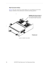
Figure 8 Controller Tray Interface Connectors
RS-232
Interface
Connectors
Ethernet
Interface
Connectors
012
3
Host Interface Connectors
DB-9
Connectors
GBIC
Connectors
Host Interface
Host minihubs
Drive Interface
Drive minihubs
012
3
Drive Interface Connectors