


26
User's Guide HDSP System Multiface II © RME
12.5 Digital Recording
Unlike analog soundcards which produce empty wave files (or noise) when no input signal is
present, digital I/O cards always need a valid input signal to start recording.
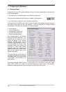
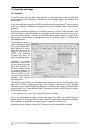
To take this into account, RME included a comprehensive I/O signal status display (showing
sample frequency, lock and sync status) in the Settings dialog, and status LEDs for each input.
If a 48 kHz signal is fed to the input and the application is set to 44.1 kHz, Check Input stops the
system from recording. This prevents faulty takes, which often go unnoticed until later on in the
production. Such tracks appear to have the wrong playback rate - the audio quality as such is
not affected.
The sample frequency shown in the Settings dialog (see chapter 11, screenshot Settings) is
useful as a quick display of the current configuration (the box itself and all connected external
equipment). If no sample frequency is recognized, it will read ‘No Lock’.
This way, configuring any suitable audio application for digital recording is simple. After select-
ing the required input, Hammerfall DSP displays the current sample frequency. This parameter
can then be changed in the application’s audio attributes (or similar) dialog.
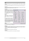
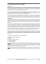
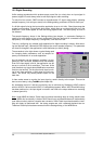
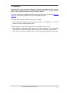
The screenshot to the right shows a typical dialog used
for changing basic parameters such as sample fre-
quency and resolution in an audio application.
Any bit resolution can be selected, providing it is sup-
ported by both the audio hardware and the software.
Even if the input signal is 24 bit, the application can still
be set to record at 16-bit resolution. The lower 8 bits
(and therefore any signals about 96dB below maximum
level) are lost entirely. On the other hand, there is noth-
ing to gain from recording a 16-bit signal at 24-bit reso-
lution - this would only waste precious space on the
hard disk.
It often makes sense to monitor the input signal or send it directly to the output. This can be
done at zero latency using TotalMix (see chapter 28).
An automated control of real-time monitoring can be achieved by Steinberg’s ASIO protocol
with our ASIO 2.0 drivers and all ASIO 2.0 compatible programs. When 'ASIO Direct Monitoring'
has been switched on, the input signal is routed in real-time to the output whenever a recording
is started (punch-in).
Note
: Under MME the feature 'Check Input' prevented recordings done at wrong sample rates.
Under WDM this functionality is limited. With Check Input activated Windows will automatically
(and without notice) perform a sample rate conversion. With Check Input deactivated the recor-
ding will simply be performed with the wrong sample rate, with a detuned playback later on.
Therefore Check Input has been removed from the Settings dialog of the WDM driver.