


User's Guide HDSP System Multiface II © RME
65
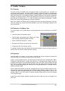
29. TotalMix: The Matrix
29.1 Overview
The mixer window of TotalMix looks and operates similar to mixing desks, as it is based on a
conventional stereo design. The matrix display presents a different method of assigning and
routing channels, based on a single channel or monaural design. The matrix view of the HDSP
looks and works like a conventional patchbay, adding functionality way beyond comparable
hardware and software soutions. While most patchbays will allow you to connect inputs to out-
puts with just the original level (1:1, or 0 dB, as known from mechanical patchbays), TotalMix
allows you to use a freely definable gain value per crosspoint.
Matrix and TotalMix are different ways of displaying the same processes. Because of this both
views are always fully synchronized. Each change in one view is immediately reflected in the
other view as well.
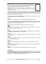
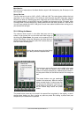
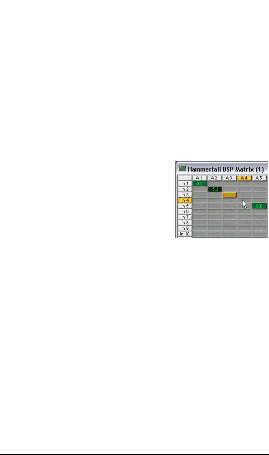
29.2 Elements of the Matrix View
The visual design of the TotalMix Matrix is mainly determined by the architecture of the HDSP
system:
• Horizontal labels: All hardware outputs
• Vertical labels: All hardware inputs. Below are all play-
back channels (software playback channels)
• Green 0.0 dB field: Standard 1:1 routing
• Black gain field: Shows the current gain value as dB
• Orange gain field: This routing is muted.
To maintain overview when the window size has been reduced, the left and upper labels are
floating. They won't left the visible area when scrolling.
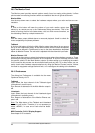
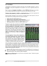
29.3 Operation
Using the Matrix is a breeze. It is very easy to indentify the current crosspoint, because the
outer labels light up in orange according to the mouse position.
If input 1 is to be routed to output 1, use the mouse and click one time on crosspoint In 1 / An 1.
The green 0.0 dB field pops in, another click removes it. To change the gain (equals the use of
a different fader position, see simultaneous display of the mixer view), hold Ctrl down and drag
the mouse up or down, starting from the gain field. The value within the field changes accord-
ingly. The corresponding fader in the mixer view is moving simultaneously, in case the currently
modified routing is visible.
Note the difference between the left side, representing the inputs and software playback chan-
nels, and the upper side, representing the hardware outputs. Moving a fader in row 1 or 2 in
TotalMix view, only the specific levels (max. 2) of this routing will change within the Matrix. But
moving a fader in row 3 will make all vertically activated levels move at once (for example
19/20, Phones output).
A gain field marked orange indicates activated mute status. Mute can only be changed in the
mixer view.